Introduction to PCB Copper Foil
Printed Circuit Boards (PCBs) are the backbone of modern electronics, providing a platform for interconnecting electronic components. One of the critical elements in PCB fabrication is the copper foil, which serves as the conductive layer for electrical signals. In high-frequency applications, the choice of PCB copper foil becomes even more crucial, as it directly impacts signal integrity, power handling, and overall performance. This article explores the various types of PCB copper foil suitable for high-frequency design, their properties, and their applications.
Importance of Copper Foil in High-Frequency PCBs
In high-frequency PCB design, the copper foil plays a vital role in ensuring optimal signal transmission and minimizing losses. The key characteristics of copper foil that affect high-frequency performance include:
- Conductivity: Copper foil with high conductivity minimizes resistive losses and ensures efficient signal propagation.
- Surface roughness: Smooth copper foil surfaces reduce skin effect losses and improve signal integrity at high frequencies.
- Thickness uniformity: Consistent copper foil thickness helps maintain controlled impedance and reduces signal reflections.
Selecting the appropriate type of PCB copper foil based on these properties is essential for achieving reliable high-frequency performance.
Types of PCB Copper Foil
There are several types of PCB copper foil available, each with its unique characteristics and suitability for high-frequency applications. Let’s explore the most common types:
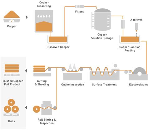
Electrodeposited (ED) Copper Foil
Electrodeposited (ED) copper foil is the most widely used type in PCB manufacturing. It is produced by electroplating copper onto a rotating drum or a stainless-steel cathode. ED copper foil is known for its excellent mechanical properties, such as high tensile strength and elongation, making it suitable for flexible and rigid-flex PCBs.
| Property | Value |
|---|---|
| Thickness | 18-350 µm |
| Tensile Strength | 250-400 MPa |
| Elongation | 2-15% |
However, ED copper foil has a relatively rough surface compared to other types, which can lead to increased skin effect losses at high frequencies. To mitigate this, manufacturers often apply surface treatments, such as reverse treat or double treat, to smooth the surface and enhance high-frequency performance.
Rolled Annealed (RA) Copper Foil
Rolled Annealed (RA) copper foil is manufactured by rolling and annealing high-purity copper ingots. The rolling process results in a smoother surface finish compared to ED copper foil, making RA foil an excellent choice for high-frequency applications. The smooth surface minimizes skin effect losses and improves signal integrity.
| Property | Value |
|---|---|
| Thickness | 12-210 µm |
| Tensile Strength | 200-300 MPa |
| Elongation | 1-5% |
RA copper foil also exhibits lower surface roughness values, typically in the range of 0.2-0.5 µm, compared to ED copper foil, which can have roughness values of 1-2 µm. This lower surface roughness contributes to better high-frequency performance.
Reverse Treated (RT) Copper Foil
Reverse Treated (RT) copper foil is a type of ED copper foil that undergoes an additional surface treatment process. The treatment involves applying a thin layer of zinc or chrome on the shiny side of the foil, followed by a passivation layer. This process results in a smoother surface finish and improved adhesion to the dielectric substrate.
RT copper foil offers several advantages for high-frequency PCBs:
- Reduced skin effect losses due to the smooth surface
- Enhanced signal integrity and reduced signal distortion
- Improved adhesion to the substrate, reducing the risk of delamination
The surface roughness of RT copper foil typically ranges from 0.5-1 µm, which is lower than standard ED copper foil but higher than RA copper foil.
Very Low Profile (VLP) Copper Foil
Very Low Profile (VLP) copper foil is a specialized type of ED copper foil designed for high-frequency applications. VLP foil undergoes a unique surface treatment process that creates an extremely smooth surface finish, with surface roughness values as low as 0.1-0.3 µm.
The benefits of VLP copper foil for high-frequency PCBs include:
- Minimal skin effect losses due to the ultra-smooth surface
- Excellent signal integrity and reduced signal attenuation
- Improved impedance control and reduced signal reflections
VLP copper foil is particularly suited for high-speed digital circuits, RF and microwave applications, and advanced packaging technologies like chip-on-board (COB) and flip-chip mounting.

Selecting the Right PCB Copper Foil for High-Frequency Design
When choosing the appropriate PCB copper foil for high-frequency design, consider the following factors:
- Frequency range: Select a copper foil with a surface roughness that minimizes skin effect losses at the target operating frequency.
- Signal integrity requirements: Opt for smoother copper foil surfaces to reduce signal distortion and improve signal integrity.
- Manufacturing process: Consider the compatibility of the copper foil with the desired PCB fabrication process and the dielectric materials used.
- Cost considerations: Balance the performance benefits of specialized copper foils with the associated costs and production volume requirements.
FAQ
1. What is the difference between ED and RA copper foil?
ED copper foil is produced by electroplating, while RA copper foil is manufactured by rolling and annealing high-purity copper ingots. RA copper foil has a smoother surface finish compared to ED copper foil, making it more suitable for high-frequency applications.
2. How does surface roughness affect high-frequency performance?
Surface roughness impacts skin effect losses at high frequencies. A smoother copper foil surface reduces skin effect losses, improves signal integrity, and minimizes signal attenuation.
3. What is the advantage of using RT copper foil?
RT copper foil offers a smoother surface finish compared to standard ED copper foil, reducing skin effect losses and enhancing signal integrity. It also provides improved adhesion to the dielectric substrate, reducing the risk of delamination.
4. When should I consider using VLP copper foil?
VLP copper foil is recommended for high-frequency applications that demand minimal skin effect losses, excellent signal integrity, and tight impedance control. It is particularly suitable for high-speed digital circuits, RF and microwave applications, and advanced packaging technologies.
5. How do I select the right PCB copper foil for my high-frequency design?
When selecting PCB copper foil for high-frequency design, consider factors such as the target operating frequency, signal integrity requirements, compatibility with the manufacturing process and dielectric materials, and cost considerations. Choose a copper foil with a surface roughness that minimizes losses and ensures optimal performance for your specific application.
Conclusion
PCB copper foil plays a critical role in high-frequency design, influencing signal integrity, power handling, and overall performance. Understanding the different types of PCB copper foil, their properties, and their suitability for various applications is essential for making informed decisions during the PCB design process. By selecting the appropriate copper foil based on factors such as surface roughness, conductivity, and thickness uniformity, designers can optimize their high-frequency PCBs for reliable and efficient operation.
As high-frequency electronics continue to advance, the development of new and improved PCB copper foil technologies will be crucial in meeting the ever-increasing demands for signal integrity and performance. Designers must stay updated with the latest advancements in copper foil manufacturing and surface treatment processes to leverage their benefits in high-frequency PCB design.
In summary, the choice of PCB copper foil is a critical consideration in high-frequency design, directly impacting the performance and reliability of electronic systems. By carefully evaluating the requirements of the application and selecting the most suitable copper foil type, designers can ensure optimal high-frequency performance and unlock the full potential of their PCB designs.
No responses yet