Introduction to TRIACs
A TRIAC, which stands for TRIode for Alternating Current, is a three-terminal semiconductor device that can conduct current in either direction when triggered by a gate pulse. TRIACs are widely used for AC power control applications such as light dimmers, motor speed controls, and temperature regulation systems.
How TRIACs Work
TRIACs have three terminals:
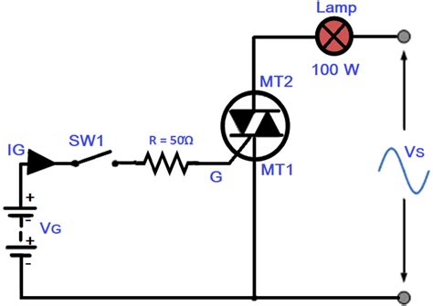
- Main Terminal 1 (MT1) – Also called Anode 1
- Main Terminal 2 (MT2) – Also called Anode 2
- Gate (G)
When a small current is applied between the gate and MT1, it triggers the TRIAC into conduction, allowing current to flow between MT1 and MT2 in either direction. Once triggered, the TRIAC will continue to conduct until the current flowing through it drops below a certain threshold called the holding current.
Some key characteristics of TRIACs include:
- Bidirectional current flow
- High current handling capability
- Triggered by low gate current
- Compact and economical AC power control
- Available in various voltage and current ratings
TRIAC Circuit Symbols
To represent TRIACs in circuit diagrams and schematics, standardized symbols are used. Understanding these symbols is essential for designing, analyzing, and troubleshooting circuits that incorporate TRIACs.
Basic TRIAC Symbol
The most basic and widely used TRIAC symbol resembles a diode bridge with a gate connection:
   /^\
  / | \
A1 / | \ A2
\ |G /
_|_/
|
- A1 and A2 represent the main terminals (MT1 and MT2)
- G represents the gate terminal
- The arrow on the gate points in the direction of conventional current flow when the gate is positive with respect to MT1
This symbol clearly shows the bidirectional nature of the TRIAC and the control provided by the gate terminal.
IEC TRIAC Symbol
The International Electrotechnical Commission (IEC) defines an alternate TRIAC symbol in their standard IEC 60617:
+ -
A1 –\/– A2
/ |
\ | G
\ /
–
- The main terminals A1 and A2 are shown with polarity symbols + and –
- The gate terminal G is connected between the main terminals
- The angled lines represent the bidirectional conduction paths
While less common than the basic symbol, the IEC symbol is recognized internationally.
Simplified TRIAC Symbols
In some cases, simplified versions of the TRIAC symbol may be used to reduce clutter in complex schematics:
A1 –( )– A2
G
A1 —-|<|— A2
These symbols still convey the essential information – two main terminals with a gate connection for triggering.

TRIAC Triggering Modes
TRIACs can be triggered into conduction using different methods, depending on the polarity of the gate signal with respect to MT1 and the quadrant of operation. The four triggering modes are:
| Mode | Gate Polarity | MT2 Polarity | Quadrant |
|---|---|---|---|
| I | Positive | Positive | 1st |
| II | Positive | Negative | 2nd |
| III | Negative | Negative | 3rd |
| IV | Negative | Positive | 4th |
Triggering sensitivity varies between modes, with modes I and III generally being more sensitive than modes II and IV. Datasheets specify gate trigger current and voltage for each mode.
Gate Triggering Circuits
To control the conduction angle and output power of a TRIAC, various gate triggering circuits can be employed:
-
Resistance Triggering: A resistor between the gate and one main terminal. Simple but lacks precise control.
-
RC Phase-Shift Triggering: Resistor-capacitor network creates a phase-shifted gate voltage. Provides improved control over conduction angle.
-
Diac Triggering: A diode for alternating current (Diac) triggers the TRIAC at a specific breakover voltage. Offers more consistent triggering.
-
Opto-isolated Triggering: An optocoupler isolates the control circuit from the power circuit. Enables safe, low-voltage control of high-power TRIACs.
The choice of triggering circuit depends on factors such as desired level of control, power level, isolation requirements, and cost.

TRIAC Applications
TRIACs find use in a wide range of AC power control applications across industrial, commercial, and consumer sectors.
Lighting Control
TRIACs are commonly used in dimmer switches for controlling the brightness of lamps and LED lights. By adjusting the conduction angle, the average power delivered to the light can be varied smoothly from zero to maximum.
Example circuit:
Lamp
Live —+ MT2
| |
/ \ |
R \G/ |
/\ / \
| A1 Neutral
TRIAC |
|
|_
Dimmer
Potentiometer
The dimmer potentiometer varies the gate trigger phase angle, controlling lamp brightness.
Motor Speed Control
TRIACs can regulate the speed of AC motors by adjusting the voltage applied to the motor windings. This is useful in applications such as fans, blowers, and power tools.
Example circuit:
Motor
Live —+ A2
| |
/ \ |
C \G/ |
/_\ |
/ A1 \
R | \
| | Neutral
|
DIAC
The RC network and diac provide phase-shifted triggering to control motor speed.
Temperature Control
In heating appliances like soldering irons, ovens, and coffee makers, TRIACs can regulate temperature by switching heater elements on and off rapidly. A temperature sensor provides feedback to the control circuit.
Example circuit:
Heater
Live —+—+
| |
/ \ |
R \G/ |
/_\ |
| |
A1 A2
|
+— Neutral
The temperature sensor (not shown) adjusts the triggering phase angle to maintain the desired temperature.
Power Converters
TRIACs are used in solid-state relays (SSRs) for switching AC loads. They provide fast, silent, and wear-free operation compared to electromechanical relays.
In AC-AC converters and static voltage regulators, TRIACs control the transfer of power between input and output by phase angle regulation.

TRIAC Selection Considerations
When choosing a TRIAC for a specific application, several key parameters must be considered:
-
Voltage Rating: The TRIAC must withstand the maximum expected voltage across main terminals in both forward and reverse directions (VDRM and VRRM).
-
Current Rating: The average and peak current handling capability (IRMS and ITSM) should exceed the load requirements with a safe margin.
-
Gate Trigger Current: The minimum gate current required to trigger the TRIAC (IGT) must be compatible with the triggering circuit.
-
Holding Current: The minimum current required to maintain conduction (IH) should be lower than the expected load current.
-
Power Dissipation: The maximum power the TRIAC can dissipate (PD) must be sufficient for the application, considering ambient temperature and heat sinking.
-
Commutating dV/dt: The maximum rate of voltage change (dV/dt) during commutation should be within the device’s specified limits to avoid unwanted triggering.
Other factors like package type, isolation voltage, and Mounting Method also influence TRIAC selection. Always consult the device datasheet and application notes for detailed specifications and guidance.
TRIAC Protection Considerations
While TRIACs are rugged devices, they are susceptible to damage or malfunction under certain conditions. Proper circuit design and protection measures are essential for reliable operation.
dV/dt Limiting
Rapid voltage changes across a TRIAC’s main terminals can cause unwanted triggering, leading to loss of control or device failure. A Snubber Circuit, consisting of a resistor and capacitor in series, can limit the dV/dt to safe levels.
   TRIAC
    / \
Live \G/ | Load
/_\ |
/ | Neutral
| R|C
Snubber
The snubber R and C values are chosen based on the TRIAC’s dV/dt rating and the expected voltage transients in the circuit.
Overcurrent Protection
TRIACs can fail short-circuit if their surge current rating is exceeded. A fast-acting fuse in series with the TRIAC can provide overcurrent protection.
| Live — | FUSE | —+—–+ |
|---|---|---|
| / \ | ||
| Load \G/ | ||
| /_\ | ||
| A1 | ||
| +—–+—– Neutral |
The fuse should be rated to blow quickly at currents above the TRIAC’s ITSM rating.
Overvoltage Protection
Voltage transients exceeding the TRIAC’s VDRM or VRRM ratings can cause punch-through failure. A varistor (MOV) or transient voltage suppressor (TVS) connected across the main terminals can clamp overvoltages to safe levels.
MOV/TVS
| Live —+—+—– | > | —+—-+ |
|---|---|---|
| / \ | ||
| Load \G/ | ||
| /_\ | ||
| A1 A2 | ||
| +——————-+— Neutral |
The MOV or TVS should be selected based on the expected transient voltage levels and the TRIAC’s maximum ratings.
Heat Sinking
TRIACs dissipate power as heat during operation, raising the junction temperature. If the junction temperature exceeds the maximum rated value (Tjmax), the device may fail. A heat sink can help dissipate excess heat and maintain a safe operating temperature.
The size and type of heat sink required depends on factors like the TRIAC’s power dissipation, ambient temperature, and airflow conditions. Thermal resistance calculations and datasheets provide guidance on heat sink selection.
TRIAC Failure Modes and Troubleshooting
Understanding common TRIAC failure modes and their symptoms aids in troubleshooting and repair of faulty circuits.
Short-Circuit Failure
A TRIAC that has failed short-circuit will conduct in both directions continuously, regardless of the gate signal. This can result in the load remaining permanently on or drawing excessive current.
Possible causes of short-circuit failure include:
- Overcurrent or surge current exceeding the device ratings
- Overvoltage transients
- Inadequate heat sinking leading to thermal runaway
- Incorrect snubber design allowing high dV/dt
To diagnose a short-circuit failure:
- Disconnect power and remove the TRIAC from the circuit.
- Use a multimeter in diode test mode to check resistance between MT1 and MT2 in both directions. A short-circuit failure will show low resistance in both directions.
Remedy: Replace the TRIAC with a new device of the same or higher ratings. Verify proper snubber design and overcurrent protection.
Open-Circuit Failure
An open-circuit TRIAC will not conduct in either direction, regardless of the gate signal. The load will remain off, and the TRIAC will appear as a high resistance.
Possible causes of open-circuit failure include:
- Excessive gate current or voltage
- Electrostatic discharge (ESD) damage
- Overheating or thermal cycling fatigue
To diagnose an open-circuit failure:
- Disconnect power and remove the TRIAC from the circuit.
- Use a multimeter in diode test mode to check resistance between MT1 and MT2 in both directions, and between gate and MT1. An open-circuit failure will show high resistance in all cases.
Remedy: Replace the TRIAC with a new device of the same or higher ratings. Ensure proper gate drive conditions and ESD handling precautions.
Half-Wave Conduction Failure
A TRIAC that conducts in only one direction or quadrant may have suffered partial damage or degradation. This can result in the load receiving half-wave power, leading to reduced performance or overheating.
Possible causes of half-wave conduction failure include:
- Device aging or degradation over time
- Exposure to excessive temperatures
- Marginal triggering conditions
To diagnose half-wave conduction:
- Disconnect the load and connect a resistor across the TRIAC’s main terminals.
- Apply a gate trigger signal and observe the voltage across the resistor on an oscilloscope. A healthy TRIAC will show symmetrical conduction in both half-cycles, while a faulty device will conduct in only one direction.
Remedy: Replace the TRIAC with a new device of the same or higher ratings. Verify proper triggering circuit design and gate drive characteristics.
FAQ
Q: What is the difference between a TRIAC and an SCR (Silicon Controlled Rectifier)?
A: While both TRIACs and SCRs are thyristors used for power control, they differ in their conduction characteristics. An SCR conducts current in only one direction when triggered by a gate pulse, making it suitable for DC or half-wave AC control. A TRIAC, on the other hand, can conduct current in both directions when triggered, allowing full-wave AC control. TRIACs are essentially two SCRs connected in inverse-parallel configuration.
Q: Can a TRIAC be used for DC power control?
A: No, TRIACs are specifically designed for AC power control applications. Their bidirectional conduction characteristic relies on the alternating nature of the supply voltage to commutate the device off at the end of each half-cycle. For DC power control, devices like MOSFETs, BJTs, or DC-rated SSRs are more appropriate.
Q: What is the purpose of a snubber circuit in a TRIAC application?
A: A snubber circuit, consisting of a resistor and capacitor in series, is connected across a TRIAC’s main terminals to limit the rate of voltage change (dV/dt) during switching transitions. High dV/dt can cause unwanted triggering of the TRIAC, leading to loss of control or device damage. The snubber absorbs voltage spikes and slows down the voltage rise, keeping the dV/dt within the TRIAC’s specified limits.
Q: How do I select the proper heat sink for a TRIAC?
A: Selecting the right heat sink for a TRIAC involves calculating the power dissipation of the device under worst-case conditions and ensuring that the heat sink can maintain the junction temperature below the maximum rated value. Key factors to consider include:
- TRIAC’s maximum power dissipation (PD)
- Maximum expected ambient temperature (TA)
- Thermal resistance from junction to case (RθJC)
- Thermal resistance from case to heat sink (RθCS)
- Thermal resistance of the heat sink (RθSA)
The required heat sink thermal resistance can be calculated using the formula:
RθSA = (TJ(max) – TA(max)) / PD – RθJC – RθCS
Refer to the TRIAC datasheet and heat sink manufacturer data to select a suitable heat sink that meets the calculated thermal resistance requirement.
Q: Can a damaged or failed TRIAC be repaired?
A: In most cases, a damaged or failed TRIAC cannot be repaired and must be replaced with a new device. TRIACs are semiconductor devices with complex internal structures, and attempting to repair them is impractical and unreliable. When replacing a faulty TRIAC, ensure that the new device has the same or better voltage and current ratings, package type, and triggering characteristics as the original. Also, verify that the root cause of the failure (e.g., overcurrent, overvoltage, insufficient heat sinking) has been addressed to prevent a recurrence.
Conclusion
TRIACs are versatile and economical semiconductor devices widely used for AC power control in various applications. Understanding TRIAC symbols, triggering modes, selection criteria, and protection requirements is crucial for designing reliable and efficient power control circuits.
By following best practices for TRIAC circuit design, such as proper device selection, snubber sizing, overcurrent and overvoltage protection, and heat sink provisioning, designers can harness the benefits of TRIACs while ensuring safe and robust operation.
When troubleshooting TRIAC circuits, a systematic approach based on understanding common failure modes and their symptoms can help identify and resolve issues quickly. Proper diagnosis and replacement of faulty devices, along with addressing the underlying causes of failure, are essential for maintaining the long-term reliability of TRIAC-
No responses yet