Introduction to the TL431 Voltage Reference
The TL431 is a versatile, adjustable shunt voltage reference widely used in power supply regulation, voltage monitoring, and various analog circuits. This guide aims to provide beginners with a comprehensive understanding of the TL431, its characteristics, and its applications in different circuits.
Key Features of the TL431
- Adjustable output voltage range: 2.5V to 36V
- Low temperature coefficient: typically 50 ppm/°C
- Low output noise
- Excellent long-term stability
- Available in various packages: TO-92, SOT-23, etc.
How the TL431 Works
The TL431 consists of a precision voltage reference, an error amplifier, and a series pass transistor. The device maintains a constant reference voltage (Vref) of 2.5V between its reference (REF) and anode (A) terminals. By adjusting the resistance ratio of an external voltage divider, the output voltage can be set to any desired value above 2.5V.
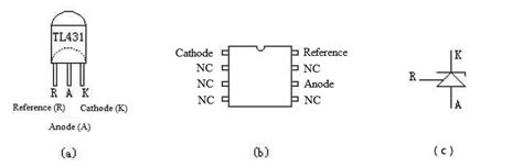
TL431 Pin Configuration
| Pin | Name | Function |
|---|---|---|
| 1 | Cathode | Connected to the negative supply voltage |
| 2 | Anode | Reference input |
| 3 | Ref | Reference output (2.5V) |

Basic TL431 Circuit
A basic TL431 circuit consists of the TL431, two resistors (R1 and R2), and a load connected to the cathode. The output voltage (Vout) is determined by the following equation:
Vout = 2.5V × (1 + R1 / R2)
To calculate the resistor values for a desired output voltage, use these formulas:
R1 = (Vout – 2.5V) × R2 / 2.5V
R2 = 2.5V × R1 / (Vout – 2.5V)
Example: To set Vout to 5V with R2 = 1kΩ, calculate R1:
R1 = (5V – 2.5V) × 1kΩ / 2.5V = 1kΩ

TL431 as a Voltage Regulator
The TL431 can be used as a simple voltage regulator by adding a pass transistor and a few additional components. This configuration allows for higher output currents and improved regulation.
Adjustable Voltage Regulator Circuit
[Include a schematic of an adjustable voltage regulator using the TL431]
In this circuit, the TL431 controls the base of the pass transistor (Q1) to maintain a constant output voltage. The output voltage is set by the R1 and R2 voltage divider, as described in the previous section.

TL431 as a Voltage Monitor
The TL431 can be used to monitor a voltage and trigger an action when a specific threshold is reached. This is useful in undervoltage or overvoltage protection circuits.
Overvoltage Protection Circuit
[Include a schematic of an overvoltage protection circuit using the TL431]
When the monitored voltage exceeds the threshold set by the R1 and R2 divider, the TL431 conducts, activating the SCR (silicon-controlled rectifier) and disconnecting the load from the supply voltage.
TL431 in Power Supply Feedback Loops
The TL431 is often used in the feedback loop of switch-mode power supplies (SMPS) to provide precise output voltage regulation. It compares a fraction of the output voltage with its internal reference and adjusts the duty cycle of the PWM (pulse-width modulation) controller accordingly.
TL431 in a Flyback Converter
[Include a simplified schematic of a flyback converter with a TL431 in the feedback loop]
In this example, the TL431 senses the output voltage through the R1 and R2 divider and controls the duty cycle of the PWM controller (e.g., TOPSwitch, VIPer, etc.) to maintain a constant output voltage.
Frequently Asked Questions (FAQ)
- What is the minimum output voltage of the TL431?
-
The minimum output voltage of the TL431 is 2.5V, which is its internal reference voltage (Vref).
-
Can the TL431 be used as a constant current source?
-
Yes, the TL431 can be configured as a constant current source by adding a sense resistor in series with the load and connecting the TL431’s REF pin to the sense resistor.
-
How accurate is the TL431’s internal reference voltage?
-
The TL431’s internal reference voltage has a typical accuracy of ±0.5% at 25°C and a temperature coefficient of 50 ppm/°C.
-
What is the maximum cathode current of the TL431?
-
The maximum cathode current of the TL431 depends on the package. For the TO-92 package, it is typically 100 mA, while for the SOT-23 package, it is around 50 mA.
-
Can multiple TL431s be used in parallel for higher current capability?
- Yes, multiple TL431s can be connected in parallel to increase the current capability. However, it is recommended to use a small balancing resistor (e.g., 10Ω) in series with each TL431’s anode to ensure proper current sharing.
Conclusion
The TL431 is a simple yet powerful device that finds applications in various analog circuits, from voltage regulation and monitoring to power supply feedback loops. By understanding its working principles and basic configurations, beginners can effectively utilize the TL431 in their designs. This guide has covered the essential aspects of the TL431, providing a solid foundation for further exploration and implementation of this versatile voltage reference.
No responses yet