What is the TL072?
The TL072 is a dual high-performance JFET-input operational amplifier IC manufactured by Texas Instruments. It features two independent op-amps in a single 8-pin package, making it a compact and cost-effective solution for many analog circuit designs. The TL072’s key characteristics include:
- Low noise: The TL072 has a low input noise voltage of 18 nV/√Hz, making it suitable for low-noise applications.
- High Input impedance: With a typical input impedance of 10^12 Ω, the TL072 minimizes loading effects on the signal source.
- Wide bandwidth: The TL072 has a unity-gain bandwidth of 3 MHz, allowing it to handle a wide range of frequencies.
- Low input bias current: The JFET-input stage results in a low input bias current of 65 pA, reducing offset voltage and drift.
TL072 Pinout and Pin Functions
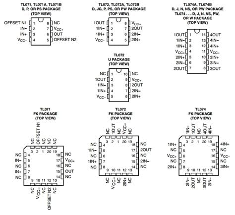
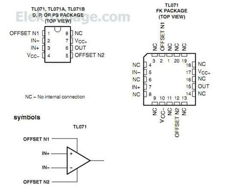
The TL072 comes in an 8-pin dual in-line package (DIP) or surface-mount package (SOIC). The pinout and pin functions are as follows:
| Pin Number | Pin Name | Function |
|---|---|---|
| 1 | OUT A | Output of op-amp A |
| 2 | IN- A | Inverting input of op-amp A |
| 3 | IN+ A | Non-inverting input of op-amp A |
| 4 | V- | Negative power supply |
| 5 | IN+ B | Non-inverting input of op-amp B |
| 6 | IN- B | Inverting input of op-amp B |
| 7 | OUT B | Output of op-amp B |
| 8 | V+ | Positive power supply |
Power Supply
The TL072 can operate with a wide range of power supply voltages, typically between ±5 V and ±15 V. The maximum power supply voltage is ±18 V. It is essential to provide a clean and stable power supply to ensure optimal performance and minimize noise. Decoupling capacitors should be placed close to the IC’s power supply pins to suppress high-frequency noise and prevent oscillations.
Input and Output
The TL072 features two independent op-amps, each with an inverting (IN-) and non-inverting (IN+) input. The input stage is a JFET differential pair, which provides high input impedance and low input bias current. The output stage is a Push-Pull Amplifier capable of driving loads down to 2 kΩ.
TL072 Specifications
Electrical Characteristics
| Parameter | Conditions | Min | Typ | Max | Unit |
|---|---|---|---|---|---|
| Input Offset Voltage | VCM = 0 V, VO = 0 V | – | 3 | 6 | mV |
| Input Bias Current | VCM = 0 V | – | 65 | 200 | pA |
| Input Impedance | – | – | 10^12 | – | Ω |
| Slew Rate | AV = +1 | – | 13 | – | V/μs |
| Gain-Bandwidth Product | – | – | 3 | – | MHz |
| Supply Current | RL = ∞ | – | 2.8 | 5 | mA |
Absolute Maximum Ratings
| Parameter | Rating | Unit |
|---|---|---|
| Supply Voltage | ±18 | V |
| Input Voltage Range | ±15 | V |
| Differential Input Voltage | ±30 | V |
| Output Short-Circuit Duration | Continuous | – |
| Operating Temperature Range | -40 to +85 | °C |
| Storage Temperature Range | -65 to +150 | °C |

TL072 Applications
The TL072’s versatility makes it suitable for a wide range of analog circuit applications, including:
Audio Systems
The TL072’s low noise and wide bandwidth make it an excellent choice for audio applications, such as:
- Preamplifiers
- Active filters
- Equalizers
- Mixers
- Tone controls
Signal Conditioning
The TL072 can be used to condition signals from various sensors and transducers, such as:
- Temperature Sensors
- Pressure sensors
- Strain gauges
- Accelerometers
- Photodiodes
Control Systems
The TL072 can be employed in control systems to implement:
- PID controllers
- Servo amplifiers
- Voltage comparators
- Oscillators
- Voltage regulators
Instrumentation
The TL072’s low input bias current and high input impedance make it suitable for instrumentation applications, including:
- Medical equipment
- Data acquisition systems
- Precision measurement devices
- Analog-to-digital converters (ADCs)
- Digital-to-analog converters (DACs)
TL072 Circuit Examples
Non-Inverting Amplifier
A non-inverting amplifier using the TL072 can be implemented as follows:
The gain of the non-inverting amplifier is given by:
Gain = 1 + (R2 / R1)
Active Low-Pass Filter
An active low-pass filter using the TL072 can be designed as follows:
The cut-off frequency of the low-pass filter is given by:
fc = 1 / (2π × R × C)
TL072 Maintenance and Troubleshooting
To ensure optimal performance and longevity of your TL072-based circuits, consider the following maintenance and troubleshooting tips:
-
Ensure a clean and stable power supply. Use decoupling capacitors close to the IC’s power supply pins to suppress noise and prevent oscillations.
-
Protect the inputs from excessive voltage levels. Always ensure that the input voltages remain within the specified limits to prevent damage to the IC.
-
Use appropriate heat sinking when operating the TL072 at high temperatures or with high output currents to prevent thermal damage.
-
Regularly inspect the circuit board for any signs of damage, such as cracked solder joints, damaged traces, or corrosion. Repair or replace components as necessary.
-
When troubleshooting, start by checking the power supply voltages and ensuring that they are within the specified range. Then, check the input and output signals using an oscilloscope to identify any anomalies.
-
If the circuit exhibits excessive noise or oscillations, check the layout and grounding of the circuit board. Ensure that the ground paths are as short as possible and that there is proper shielding between sensitive signal traces.
Frequently Asked Questions (FAQ)
-
Q: What is the difference between the TL072 and the TL082?
A: The TL072 and TL082 are both dual JFET-input op-amps, but the TL082 has a higher slew rate and gain-bandwidth product, making it more suitable for high-speed applications. The TL072 is a lower-cost alternative with slightly lower performance specifications. -
Q: Can the TL072 be used with single-supply operation?
A: Yes, the TL072 can be used with single-supply operation, but the input and output voltages must be within the specified range. When using single-supply operation, it is common to use a voltage divider to bias the input signals to half the supply voltage. -
Q: What is the maximum supply voltage for the TL072?
A: The maximum supply voltage for the TL072 is ±18 V. Operating the IC beyond this voltage can result in permanent damage. -
Q: How can I reduce the noise in my TL072-based circuit?
A: To reduce noise in your TL072-based circuit, ensure a clean and stable power supply, use proper grounding techniques, and employ shielding for sensitive signal traces. Additionally, use low-noise resistors and capacitors, and keep the circuit board layout as compact as possible. -
Q: Can I replace a TL072 with a TL082 in an existing circuit?
A: In most cases, yes, you can replace a TL072 with a TL082 in an existing circuit. However, it is essential to review the specific requirements of your circuit and ensure that the TL082’s higher slew rate and gain-bandwidth product will not adversely affect the circuit’s performance.
Conclusion
The TL072 is a versatile and widely-used dual op-amp IC that offers excellent performance in a compact package. Its low noise, high input impedance, and wide bandwidth make it suitable for a broad range of analog circuit applications, from audio systems to instrumentation and control. By understanding the TL072 pinout, specifications, and applications, and following proper maintenance and troubleshooting techniques, you can effectively utilize this powerful op-amp in your designs and ensure optimal performance and reliability.
No responses yet