What is THT Mounting?
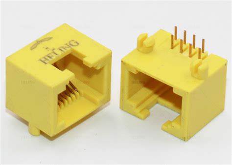
THT (Through-Hole Technology) mounting is a method of attaching electronic components to a printed circuit board (PCB) by inserting the component leads through holes drilled in the board and soldering them to pads on the opposite side. This is in contrast to Surface Mount Technology (SMT), where components are placed directly onto the surface of the PCB.
THT mounting has been used for decades and is still widely employed in various applications, particularly in situations where high mechanical strength, large components, or high power dissipation is required.
Advantages of THT Mounting
- Mechanical strength: THT components are securely fastened to the PCB, making them more resistant to vibration and physical stress.
- Ease of manual assembly: THT components are easier to handle and solder manually compared to SMT components.
- High power dissipation: THT components can typically handle higher power levels due to their larger size and better heat dissipation through the leads.
- Accessibility for repairs: THT components can be easily replaced or repaired if needed.
Disadvantages of THT Mounting
- Lower component density: THT components occupy more space on the PCB compared to SMT components, limiting the overall component density.
- Increased manufacturing time: THT assembly is generally slower than SMT assembly due to the need for manual insertion and soldering.
- Higher drilling costs: PCBs for THT mounting require holes to be drilled, which adds to the manufacturing cost.
- Limited design flexibility: THT components have fixed lead spacing, which can limit the design options for the PCB layout.
THT Components
THT components come in various shapes and sizes, each designed for specific applications. Some common types of THT components include:
- Resistors
- Capacitors
- Inductors
- Diodes
- Transistors
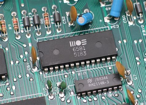
- Integrated Circuits (ICs)
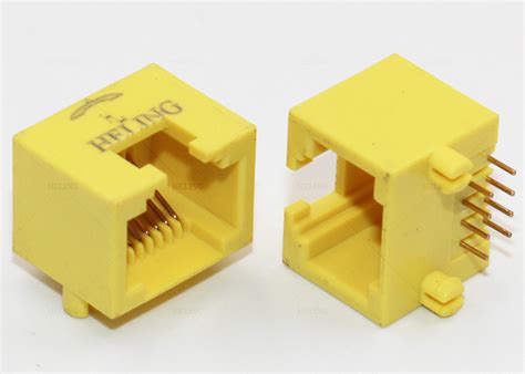
- Connectors
- Switches
These components are available in different package types, such as axial, radial, and DIP (Dual Inline Package).
Component Selection Considerations
When selecting THT components for your project, consider the following factors:
- Electrical specifications: Ensure that the component meets the required electrical characteristics, such as resistance, capacitance, or voltage rating.
- Power rating: Choose components with appropriate power ratings to handle the expected current and voltage levels in your circuit.
- Tolerance: Consider the acceptable tolerance range for the component value, as this can affect the overall performance of the circuit.
- Size: Select components that fit within the available space on your PCB and are compatible with your mounting holes.
- Environmental factors: Consider the operating temperature range, humidity, and other environmental factors that may impact component performance.
PCB Design for THT Mounting
When designing a PCB for THT mounting, several key aspects must be considered to ensure proper component placement, routing, and manufacturability.
Pad Size and Spacing
The pad size and spacing for THT components are determined by the component lead diameter and pitch. Ensure that the pads are large enough to accommodate the component leads and provide sufficient space for soldering. The pad size should also consider the manufacturing tolerances and the soldering process used.
Typical pad sizes for common THT components are:
| Component | Lead Diameter (mm) | Pad Diameter (mm) |
|---|---|---|
| Resistor | 0.5 – 0.8 | 1.5 – 2.0 |
| Capacitor | 0.5 – 1.0 | 1.5 – 2.5 |
| Transistor | 0.4 – 0.8 | 1.2 – 2.0 |
| IC | 0.4 – 0.8 | 1.2 – 2.0 |
Hole Size and Drilling
The hole size for THT components should be slightly larger than the component lead diameter to allow for easy insertion and to accommodate manufacturing tolerances. Typical hole sizes range from 0.6mm to 1.2mm, depending on the component lead diameter.
When specifying hole sizes, consider the drilling capabilities of your PCB manufacturer. Smaller hole sizes may increase the manufacturing cost or require special drilling techniques.
Routing and Clearance
When routing traces between THT components, ensure adequate clearance between the traces, pads, and holes to prevent short circuits and manufacturing issues. The minimum clearance between traces and pads depends on the PCB manufacturing capabilities and the voltage levels in the circuit.
Typical clearance values for THT PCBs are:
| Voltage Level | Minimum Clearance (mm) |
|---|---|
| < 50V | 0.2 – 0.3 |
| 50V – 150V | 0.3 – 0.6 |
| > 150V | 0.6 – 1.0 |
Silkscreen and Assembly Markings
Include clear silkscreen markings on the PCB to indicate component placement, orientation, and reference designators. This helps ensure accurate manual assembly and facilitates troubleshooting and repairs.
Consider adding polarity markings for polarized components, such as electrolytic capacitors and diodes, to prevent incorrect installation.

THT Soldering Process
The soldering process for THT components involves several steps to ensure a reliable and strong connection between the component leads and the PCB pads.
Soldering Tools and Materials
To solder THT components, you will need the following tools and materials:
- Soldering iron with a suitable tip size (typically 0.8mm to 1.6mm)
- Solder wire (lead-free or leaded, depending on the application)
- Flux (optional, but recommended for improved soldering quality)
- Solder wick or desoldering pump (for removing excess solder or correcting mistakes)
- Tweezers or pliers (for handling components)
- Cleaning supplies (isopropyl alcohol and brushes for cleaning flux residue)
Soldering Technique
-
Preheat the PCB and component leads: Touch the soldering iron tip to both the PCB pad and the component lead simultaneously to preheat them. This helps the solder flow more easily and creates a better bond.
-
Apply solder: Feed solder wire to the junction between the PCB pad and the component lead. The solder should melt and flow around the lead and pad, creating a conical shape.
-
Remove the soldering iron: Once sufficient solder has been applied, remove the soldering iron while keeping the component and PCB steady. Allow the solder joint to cool and solidify.
-
Inspect the solder joint: A good solder joint should be shiny, smooth, and have a concave profile. It should fully cover the PCB pad and the component lead without any gaps or excess solder.
Common Soldering Defects
-
Cold solder joint: Occurs when the PCB pad and component lead are not sufficiently heated before applying solder, resulting in a dull, cracked, or lumpy solder joint.
-
Bridging: Excess solder creates an unintended connection between two or more pads or leads.
-
Insufficient solder: The solder joint does not fully cover the PCB pad or component lead, leading to a weak or intermittent connection.
-
Overheated joint: Applying too much heat can damage the PCB, component, or solder joint, leading to a dull or discolored appearance.
To avoid these defects, practice proper soldering techniques, use appropriate tools and materials, and inspect the solder joints carefully after soldering.
THT Assembly Process
The THT assembly process involves several stages, from component preparation to final inspection and testing.
Component Preparation
-
Organize components: Sort the THT components according to their values, types, and reference designators to streamline the assembly process.
-
Prepare component leads: If necessary, bend or trim the component leads to fit the PCB hole spacing using pliers or lead forming tools.
PCB Preparation
-
Clean the PCB: Remove any dirt, grease, or oxidation from the PCB surface and holes to ensure proper soldering and component fitment.
-
Apply flux (optional): If using flux, apply a thin layer to the PCB pads and holes to improve solder wetting and joint quality.
Component Placement
-
Insert components: Place the THT components into their respective holes on the PCB, ensuring correct orientation and alignment.
-
Secure components: If necessary, bend the component leads on the opposite side of the PCB to hold them in place during soldering.
Soldering
-
Solder the components: Following the soldering technique described earlier, solder each component lead to its corresponding PCB pad.
-
Clean the PCB: Remove any flux residue or excess solder using isopropyl alcohol and a brush.
Inspection and Testing
-
Visual inspection: Carefully examine each solder joint for defects, such as bridging, insufficient solder, or overheated joints. Rework any defective joints as needed.
-
Electrical testing: Perform continuity tests, resistance measurements, or functional tests to ensure the assembled PCB operates as intended.
Troubleshooting and Rework
Despite careful assembly and soldering, issues may arise during the THT mounting process. Some common problems and their solutions include:
-
Component misalignment: If a component is misaligned or inserted incorrectly, desolder the component, clean the pads and holes, and reinsert the component correctly.
-
Solder bridges: Use solder wick or a desoldering pump to remove the excess solder causing the bridge. If necessary, resolder the joint.
-
Damaged components: If a component is damaged during the assembly process, desolder it and replace it with a new component.
-
Inconsistent solder joints: If solder joints appear inconsistent or defective, resolder the affected joints using proper techniques and materials.
When reworking THT components, take care not to overheat the PCB or components, as this can cause additional damage. Use a temperature-controlled soldering iron and work carefully to minimize the risk of damaging the PCB or surrounding components.
FAQ
-
Can I mix THT and SMT components on the same PCB?
Yes, it is possible to use both THT and SMT components on the same PCB. This is called a mixed-technology or hybrid assembly. However, it is essential to consider the assembly process, as THT and SMT components require different soldering techniques and equipment. -
Are there any specific design rules for THT PCBs?
Yes, when designing a PCB for THT components, consider the pad size, hole size, and spacing requirements for each component. Ensure adequate clearance between traces, pads, and holes to prevent short circuits and manufacturing issues. Consult with your PCB manufacturer for specific design guidelines. -
What are the most common soldering defects in THT assembly?
The most common soldering defects in THT assembly include cold solder joints, bridging, insufficient solder, and overheated joints. These defects can lead to poor electrical connections, intermittent operation, or complete failure of the assembled PCB. -
How can I improve the quality of my THT solder joints?
To improve the quality of your THT solder joints, use appropriate soldering tools and materials, apply proper soldering techniques, and inspect the solder joints carefully after soldering. Practice good soldering hygiene, such as keeping the soldering iron tip clean and using fresh solder wire. -
What should I do if I encounter a problem during THT assembly?
If you encounter a problem during THT assembly, such as component misalignment, solder bridges, or damaged components, carefully assess the issue and determine the best course of action. This may involve desoldering and repositioning components, removing excess solder, or replacing damaged components. Work carefully and use appropriate tools and techniques to minimize the risk of causing additional damage.
Conclusion
THT mounting is a reliable and widely used method for assembling electronic components on PCBs. By understanding the principles of THT components, PCB design considerations, soldering techniques, and assembly processes, you can create robust and functional electronic assemblies.
When working with THT components, remember to:
- Select appropriate components based on electrical specifications, power ratings, and environmental factors.
- Design the PCB with proper pad sizes, hole sizes, and clearances for THT components.
- Use appropriate soldering tools, materials, and techniques to create high-quality solder joints.
- Follow a systematic assembly process, including component preparation, placement, soldering, and inspection.
- Troubleshoot and rework any issues that arise during the assembly process, taking care to minimize damage to the PCB and components.
By following the guidelines and best practices outlined in this comprehensive guide, you can confidently tackle THT mounting projects and achieve successful results in your electronic assemblies.
No responses yet