Introduction to Thermal-Electrical Derating
Thermal-electrical derating is a critical concept in the design and operation of electrical systems and components. It involves reducing the maximum allowable electrical stress on a component based on the thermal conditions it will experience during operation. The goal is to ensure the component operates reliably over its intended lifetime by preventing overheating and premature failure.
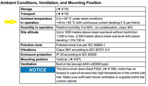
Electrical components generate heat when conducting current. This heat must be dissipated to the surrounding environment to prevent the component temperature from rising to dangerous levels. However, the ability to dissipate heat is limited by the thermal resistance between the component and its environment. As the ambient temperature increases, less heat can be dissipated, and the component temperature rises.
To account for this, components are typically derated – their maximum allowable power, current, or voltage is reduced based on the expected operating temperature. Derating helps ensure the component temperature stays within safe limits across the full range of operating conditions.
Importance of Thermal-Electrical Derating
Proper thermal-electrical derating is essential for several reasons:
-
Reliability – Operating components within their derated limits greatly reduces the risk of thermally-induced failures. This improves overall system reliability.
-
Lifetime – High temperatures accelerate various failure mechanisms such as chemical degradation and mechanical stress. Derating extends component lifetime by keeping temperatures low.
-
Safety – Overheated components can pose fire hazards or cause burns if touched. Derating maintains safe component temperatures.
-
Performance – Excessive temperatures degrade the electrical performance of many components. Derating helps maintain performance over the operating temperature range.
-
Cost – While derating may require using higher-capacity (and more expensive) components, this is offset by improved reliability, longer lifetimes, and reduced maintenance costs.
Derating Standards and Guidelines
Several industry standards and guidelines cover thermal-electrical derating. Some of the most widely used include:
- MIL-STD-975 – NASA standard for electrical component derating
- MIL-STD-1547 – U.S. military standard for electronic component derating
- IEC 60950-1 – Safety of information technology equipment
- IPC-9592 – Performance parameters for power conversion devices
These documents provide detailed derating factors and design guidelines for various component types and applications. They are an essential resource for engineers performing thermal-electrical derating analyses.

Derating Analysis Process
The thermal-electrical derating analysis process typically involves the following steps:
-
Determine operating conditions – Establish the expected ambient temperature range, airflow conditions, power dissipation, and other relevant operating factors for the component or system.
-
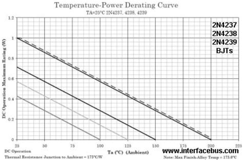
Obtain component derating data – Consult component datasheets, application notes, and derating standards to determine the maximum allowable electrical stress as a function of temperature for each component.
-
Calculate component temperatures – Use thermal analysis techniques (discussed below) to predict the temperature of each component based on its power dissipation and the system thermal conditions.
-
Apply derating factors – Reduce the maximum allowable electrical stress for each component based on its predicted operating temperature and the appropriate derating factor from step 2.
-
Verify derated design – Check that the derated component electrical stresses are within the allowable limits across the full range of operating conditions. Revise the design if necessary.
-
Document results – Prepare a report summarizing the derating analysis methodology, assumptions, results, and design decisions for future reference and design iterations.
Thermal Analysis Techniques
Predicting component temperatures is a key part of the derating analysis process. Several techniques are commonly used:
Thermal Resistance Modeling
The thermal resistance between a component and its environment can be modeled as a network of resistances, similar to an electrical circuit. Key resistances include:
- Junction-to-case (??JC) – resistance from the component’s active junction to its case
- Case-to-heatsink (??CS) – resistance from the component case to an attached heatsink
- Heatsink-to-ambient (??SA) – resistance from the heatsink to the surrounding ambient air
These resistances are used to calculate the temperature rise from ambient (TA) to the component junction (TJ) as:
TJ = TA + PD ??? (??JC + ??CS + ??SA)
Where PD is the component’s power dissipation.
Thermal resistance data is typically provided by component manufacturers and heatsink vendors. Some example values are:
| Component | ??JC (??C/W) |
|---|---|
| TO-220 | 1.5 |
| TO-263 | 0.5 |
| BGA | 0.2 |
| Heatsink | ??SA @ 200 LFM (??C/W) |
|---|---|
| 10 x 10 mm | 16 |
| 25 x 25 mm | 8 |
| 50 x 50 mm | 4 |
Computational Fluid Dynamics (CFD)
For complex systems with many components and intricate airflow paths, thermal resistance modeling may not be sufficiently accurate. In these cases, CFD software can be used to simulate the airflow and heat transfer in 3D. CFD provides detailed temperature maps of the system, allowing hot spots and recirculation zones to be identified.
CFD simulation inputs include:
- 3D solid model of the system
- Material thermal properties
- Component power dissipations
- Airflow boundary conditions
- Ambient temperature
Simulation outputs include:
- Airflow velocity and direction
- Pressure distribution
- Component and air temperatures
- Heat fluxes
Direct Temperature Measurement
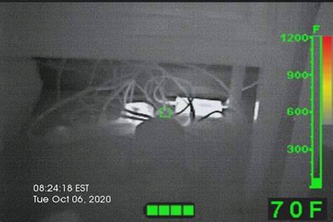
In some cases, direct measurement of component temperatures may be necessary to validate the thermal models and derating assumptions. This is typically done with thermocouples, RTDs, or infrared cameras.
Key considerations for temperature measurement include:
- Sensor placement – Sensors should be placed as close as possible to the component hot spots, while avoiding electrical interference.
- Sensor attachment – Sensors must make good thermal contact with the component without affecting its operation. Adhesives and tapes are commonly used.
- Measurement conditions – Temperatures should be measured under worst-case operating conditions, including maximum ambient temperature and power dissipation.
- Measurement accuracy – Sensor calibration and uncertainty should be considered when interpreting results. Typical accuracies are ??1-2??C.
Derating Example
To illustrate the thermal-electrical derating process, consider a TO-220 power transistor mounted to a 25 x 25 mm heatsink in a 55??C ambient environment with 200 LFM airflow. The maximum allowable junction temperature is 150??C.
The transistor has the following characteristics:
| Parameter | Value |
|---|---|
| Maximum power (PMAX) | 100 W |
| ??JC | 1.5 ??C/W |
The heatsink has a ??SA of 8 ??C/W at 200 LFM.
Assuming a ??CS of 0.5 ??C/W, the total thermal resistance from junction to ambient is:
??JA = ??JC + ??CS + ??SA = 1.5 + 0.5 + 8 = 10 ??C/W
The temperature rise from ambient to junction at maximum power is:
??T = PMAX ??? ??JA = 100 W ??? 10 ??C/W = 100??C
Thus, the junction temperature at maximum power would be:
TJ = TA + ??T = 55??C + 100??C = 155??C
This exceeds the maximum allowable junction temperature of 150??C, so derating is necessary.
The derated maximum power can be calculated as:
PDERATED = (TJ,MAX – TA) / ??JA = (150??C – 55??C) / 10 ??C/W = 9.5 W
So in this configuration, the transistor must be derated to 9.5 W to maintain a safe junction temperature.
FAQ
What is thermal-electrical derating?
Thermal-electrical derating is the practice of reducing the maximum allowable electrical stress (power, current, voltage) on a component based on its expected operating temperature. The goal is to prevent overheating and ensure reliable operation over the component’s lifetime.
Why is derating important?
Derating is important because it helps ensure component reliability, safety, and performance over a wide range of operating conditions. It reduces the risk of thermally-induced failures, extends component lifetime, and maintains electrical performance at high temperatures.
What standards cover thermal-electrical derating?
Several industry standards cover thermal-electrical derating, including MIL-STD-975 (NASA), MIL-STD-1547 (U.S. military), IEC 60950-1 (IT equipment safety), and IPC-9592 (power conversion devices). These standards provide derating factors and design guidelines for various components and applications.
How are component temperatures predicted for derating analysis?
Component temperatures can be predicted using thermal resistance modeling, computational fluid dynamics (CFD), or direct measurement. Thermal resistance modeling is the simplest approach, using a network of thermal resistances to calculate component temperature rise. CFD provides more detailed predictions for complex systems, while direct measurement is used to validate models.
What is a real-world example of thermal-electrical derating?
A common example is derating power transistors mounted on heatsinks. The maximum allowable power dissipation of the transistor is reduced based on the heatsink’s ability to dissipate heat to the ambient environment. The derated power is calculated from the junction-to-ambient thermal resistance and maximum allowable junction temperature.
No responses yet