Introduction to Signal Integrity Simulation
Signal integrity (SI) simulation is a crucial aspect of designing and validating high-speed electronic systems. As the demand for faster data transmission rates and higher bandwidth continues to grow, engineers face significant challenges in ensuring the reliability and performance of their designs. Signal integrity issues, such as crosstalk, reflections, and power integrity problems, can severely impact the functionality and quality of high-speed systems. This is where signal integrity simulation comes into play, providing designers with powerful tools to analyze, optimize, and validate their designs before physical implementation.
In this article, we will delve into the world of signal integrity simulation, exploring its fundamental concepts, techniques, and best practices. We will discuss the importance of signal integrity in high-speed design, the various types of signal integrity analysis, and the tools and methodologies used to perform these simulations. Additionally, we will cover real-world examples and case studies to illustrate the practical application of signal integrity simulation in industry.
The Importance of Signal Integrity in High-Speed Design
As the operating frequencies of electronic systems continue to increase, the effects of signal integrity become more pronounced and critical to address. High-speed signals are susceptible to various phenomena that can degrade the quality and reliability of the transmitted data. Some of the key signal integrity challenges in high-speed design include:
-
Reflections: When a signal encounters an impedance discontinuity, such as a connector or a change in trace width, a portion of the signal energy is reflected back towards the source. These reflections can cause signal distortions, overshoot, and undershoot, leading to data corruption and system failures.
-
Crosstalk: Crosstalk occurs when a signal on one trace induces unwanted voltage or current on adjacent traces through electromagnetic coupling. This interference can cause signal distortion, false switching, and reduced noise margins, compromising the integrity of the transmitted data.
-
Power Integrity: Power integrity refers to the quality and stability of the power supply network in an electronic system. Inadequate power delivery can result in voltage fluctuations, ground bounce, and electromagnetic interference (EMI), which can adversely affect signal integrity and overall system performance.
-
Timing Issues: High-speed signals are sensitive to timing variations caused by factors such as propagation delay, jitter, and skew. These timing issues can lead to setup and hold violations, resulting in data errors and system malfunctions.
To mitigate these signal integrity challenges and ensure the reliable operation of high-speed systems, designers rely on signal integrity simulation tools and techniques. By accurately modeling and analyzing the behavior of signals in the presence of various physical and electrical effects, signal integrity simulation enables engineers to identify potential issues early in the design process and take corrective actions to optimize the design.
Types of Signal Integrity Analysis
Signal integrity simulation encompasses various types of analysis techniques, each focusing on different aspects of signal behavior and system performance. The main types of signal integrity analysis include:
1. Time-Domain Analysis
Time-domain analysis is the most common and fundamental type of signal integrity simulation. It involves simulating the behavior of signals over time, considering factors such as rise and fall times, propagation delay, and signal amplitudes. Time-domain simulations help designers visualize and analyze the waveforms of signals at different points in the system, allowing them to identify issues such as reflections, crosstalk, and timing violations.
2. Frequency-Domain Analysis
Frequency-domain analysis focuses on the behavior of signals in the frequency domain, providing insights into the system’s frequency response, bandwidth, and impedance characteristics. This type of analysis is particularly useful for evaluating the performance of high-speed interconnects, such as PCB traces, cables, and connectors. By examining the frequency-dependent properties of the system, designers can optimize the design for maximum bandwidth and minimize signal distortion.
3. Statistical Analysis
Statistical analysis techniques are used to assess the impact of manufacturing variations and environmental factors on signal integrity. These variations can include tolerances in PCB fabrication, component parameters, and operating conditions such as temperature and humidity. Statistical analysis helps designers determine the robustness and reliability of their designs by predicting the likelihood of signal integrity issues under various scenarios.
4. Power Integrity Analysis
Power integrity analysis focuses on the quality and stability of the power delivery network in an electronic system. It involves simulating the behavior of the power and ground planes, decoupling capacitors, and voltage regulators to ensure that the system receives clean and stable power supply. Power integrity analysis helps designers identify and mitigate issues such as voltage drops, ground bounce, and electromagnetic interference (EMI) that can negatively impact signal integrity.
5. Electromagnetic Compatibility (EMC) Analysis
EMC analysis is concerned with the ability of an electronic system to operate properly in the presence of electromagnetic interference (EMI) and to avoid causing interference to other systems. EMC analysis involves simulating the electromagnetic fields generated by the system and evaluating their impact on signal integrity and overall system performance. This type of analysis helps designers ensure compliance with EMC regulations and standards.
Signal Integrity Simulation Tools and Methodologies
To perform signal integrity simulations, designers rely on a variety of tools and methodologies. These tools range from basic circuit simulators to advanced 3D electromagnetic field solvers, each offering specific capabilities and advantages. Some of the commonly used signal integrity simulation tools include:
1. SPICE-based Circuit Simulators
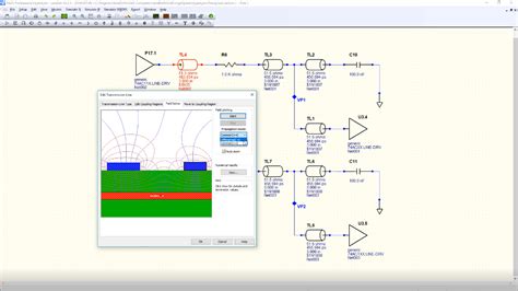
SPICE (Simulation Program with Integrated Circuit Emphasis) is a widely used circuit simulation tool that forms the basis for many commercial and open-source simulators. SPICE-based simulators, such as LTspice and PSpice, allow designers to model and simulate the behavior of electronic circuits, including high-speed interconnects and transmission lines. These tools provide time-domain and frequency-domain analysis capabilities, enabling designers to analyze signal integrity issues at the circuit level.
2. 3D Electromagnetic Field Solvers
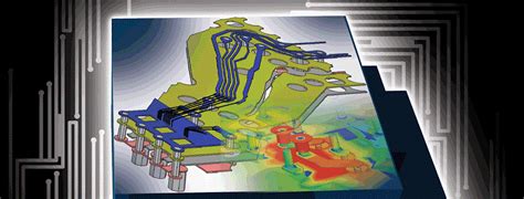
3D electromagnetic field solvers, such as Ansys HFSS and CST Studio Suite, are used to simulate the electromagnetic behavior of complex structures, including PCBs, packages, and connectors. These tools solve Maxwell’s equations in three dimensions, accurately capturing the effects of geometry, materials, and boundary conditions on signal propagation. 3D EM solvers are particularly useful for analyzing high-frequency effects, such as resonances, radiation, and coupling, which are difficult to model using circuit-based simulators.
3. Channel Simulators
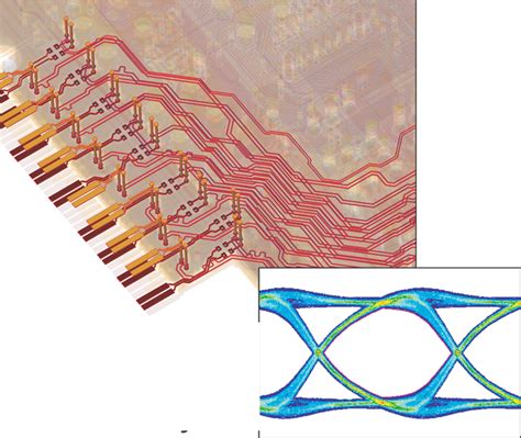
Channel simulators, such as Keysight Advanced Design System (ADS) and Cadence Sigrity, are specialized tools for simulating high-speed digital channels. These tools combine circuit simulation with advanced modeling techniques, such as behavioral models and statistical analysis, to predict the performance of high-speed links. Channel simulators enable designers to analyze signal integrity issues, such as intersymbol interference (ISI), crosstalk, and jitter, and to optimize the design of equalization and pre-emphasis circuits.
4. Power Integrity Simulators
Power integrity simulators, such as Ansys SIwave and Cadence Voltus, are used to analyze the power delivery network of electronic systems. These tools simulate the behavior of power and ground planes, decoupling capacitors, and voltage regulators, helping designers ensure the stability and quality of the power supply. Power integrity simulators enable designers to identify and mitigate issues such as voltage drops, ground bounce, and EMI, which can adversely affect signal integrity.

Best Practices for Signal Integrity Simulation
To effectively utilize signal integrity simulation in high-speed design, designers should follow certain best practices and guidelines. These best practices help ensure accurate and reliable simulation results, leading to more robust and optimized designs. Some of the key best practices for signal integrity simulation include:
1. Accurate Modeling and Characterization
The accuracy of signal integrity simulations depends heavily on the quality and fidelity of the models used. Designers should invest time and effort in creating accurate models of the components, interconnects, and materials in their design. This includes characterizing the electrical properties of PCB materials, capturing the geometry and dimensions of traces and vias, and modeling the behavior of connectors and packages. Accurate modeling ensures that the simulation results closely match the actual behavior of the system.
2. Proper Boundary Conditions and Terminations
Setting appropriate boundary conditions and terminations is crucial for obtaining valid simulation results. Designers should carefully define the input and output ports of their system, specifying the correct impedance, voltage, and current values. Proper termination schemes, such as series termination or parallel termination, should be used to minimize reflections and ensure signal integrity. Incorrectly defined boundary conditions or terminations can lead to misleading simulation results and suboptimal designs.
3. Parametric Sweeps and Sensitivity Analysis
Parametric sweeps and sensitivity analysis are powerful techniques for exploring the design space and identifying the impact of various parameters on signal integrity. Designers should perform parametric sweeps over key design variables, such as trace width, dielectric thickness, and component values, to understand their effects on signal quality. Sensitivity analysis helps identify the most critical parameters and guides designers in optimizing their designs for robustness and reliability.
4. Multi-Physics Analysis
Signal integrity is not only affected by electrical factors but also by thermal and mechanical aspects of the system. Designers should consider multi-physics analysis, which combines electrical, thermal, and mechanical simulations, to obtain a comprehensive understanding of the system’s behavior. For example, thermal effects can impact the electrical properties of materials, while mechanical stress can cause deformations and affect signal propagation. Multi-physics analysis enables designers to identify and mitigate potential issues arising from the interaction of different physical domains.
5. Collaboration and Communication
Effective signal integrity simulation requires collaboration and communication among various stakeholders, including design engineers, layout designers, and manufacturing teams. Designers should establish clear communication channels and share simulation results, design guidelines, and best practices with their colleagues. Collaboration helps ensure that signal integrity considerations are incorporated throughout the design process, from concept to manufacturing, leading to more reliable and high-performance systems.
Real-World Examples and Case Studies
To illustrate the practical application of signal integrity simulation in industry, let’s explore some real-world examples and case studies.
1. High-Speed PCB Design for Automotive Radar Systems
In the automotive industry, radar systems are increasingly used for advanced driver assistance systems (ADAS) and autonomous driving applications. These radar systems operate at high frequencies, typically in the 77-81 GHz range, and require careful signal integrity analysis to ensure reliable performance. In this case study, signal integrity simulation was used to optimize the PCB layout and stack-up of a automotive radar module.
The designers used a combination of 3D EM simulation and circuit-level simulation to analyze the high-frequency behavior of the PCB traces, vias, and antennas. They performed parametric sweeps over key design variables, such as trace width, dielectric thickness, and via geometry, to identify the optimal configuration for signal integrity. The simulation results helped the designers minimize reflections, crosstalk, and losses, ensuring robust and reliable operation of the radar system.
2. Power Integrity Analysis for High-Performance Computing Systems
In high-performance computing (HPC) systems, power integrity is a critical concern due to the high power consumption and fast switching speeds of the processors and memory devices. Poor power integrity can lead to voltage fluctuations, ground bounce, and EMI, which can degrade signal integrity and cause system instability. In this case study, power integrity simulation was used to optimize the power delivery network (PDN) of an HPC system.
The designers used a power integrity simulator to model the behavior of the power and ground planes, decoupling capacitors, and voltage regulators. They performed simulations to analyze the impedance profile of the PDN, identifying resonances and voltage fluctuations that could impact signal integrity. Based on the simulation results, the designers optimized the placement and values of decoupling capacitors, minimized the inductance of the power and ground paths, and ensured adequate voltage regulation. The optimized PDN design helped maintain signal integrity and enhance the overall performance and reliability of the HPC system.
Frequently Asked Questions (FAQ)
-
What is signal integrity, and why is it important in high-speed design?
Signal integrity refers to the ability of an electronic system to maintain the quality and reliability of signals as they propagate through interconnects and devices. In high-speed design, signal integrity is crucial because the effects of reflections, crosstalk, and power integrity issues become more pronounced at higher frequencies and data rates. Ensuring good signal integrity is essential for achieving reliable communication, minimizing data errors, and preventing system failures. -
What are the main types of signal integrity analysis?
The main types of signal integrity analysis include: - Time-domain analysis: Simulates the behavior of signals over time, considering factors such as rise and fall times, propagation delay, and signal amplitudes.
- Frequency-domain analysis: Focuses on the behavior of signals in the frequency domain, providing insights into the system’s frequency response, bandwidth, and impedance characteristics.
- Statistical analysis: Assesses the impact of manufacturing variations and environmental factors on signal integrity.
- Power integrity analysis: Focuses on the quality and stability of the power delivery network in an electronic system.
-
Electromagnetic compatibility (EMC) analysis: Evaluates the ability of an electronic system to operate properly in the presence of electromagnetic interference (EMI) and to avoid causing interference to other systems.
-
What are some common signal integrity issues in high-speed design?
Common signal integrity issues in high-speed design include: - Reflections: Occur when a signal encounters an impedance discontinuity, causing a portion of the signal energy to reflect back towards the source.
- Crosstalk: Happens when a signal on one trace induces unwanted voltage or current on adjacent traces through electromagnetic coupling.
- Power integrity problems: Inadequate power delivery can result in voltage fluctuations, ground bounce, and EMI, which can adversely affect signal integrity.
-
Timing issues: High-speed signals are sensitive to timing variations caused by factors such as propagation delay, jitter, and skew, leading to setup and hold violations.
-
What are some best practices for performing signal integrity simulations?
Some best practices for performing signal integrity simulations include: - Accurate modeling and characterization of components, interconnects, and materials.
- Setting appropriate boundary conditions and terminations to ensure valid simulation results.
- Performing parametric sweeps and sensitivity analysis to explore the design space and identify critical parameters.
- Considering multi-physics analysis to account for the interaction of electrical, thermal, and mechanical aspects of the system.
-
Collaborating and communicating with various stakeholders, including design engineers, layout designers, and manufacturing teams.
-
How can signal integrity simulation help in the design and validation of high-speed systems?
Signal integrity simulation helps in the design and validation of high-speed systems by: - Identifying potential signal integrity issues early in the design process, allowing designers to take corrective actions and optimize the design.
- Providing insights into the behavior of signals under various conditions, such as different frequencies, data rates, and environmental factors.
- Enabling designers to explore the design space and find the optimal configuration for signal integrity, considering factors such as trace geometry, dielectric properties, and component placement.
- Helping ensure compliance with industry standards and regulations related to signal integrity and EMC.
- Reducing the need for physical prototyping and testing, saving time and cost in the development process.
By leveraging signal integrity simulation techniques and following best practices, designers can effectively analyze, optimize, and validate their high-speed designs, ensuring reliable and high-performance operation of electronic systems.
Conclusion
Signal integrity simulation plays a vital role in the design and validation of high-speed electronic systems. As the demand for faster data transmission rates and higher bandwidth continues to grow, the challenges associated with signal integrity become more critical to address. By utilizing advanced simulation tools and methodologies, designers can analyze and mitigate signal integrity issues, such as reflections, crosstalk, and power integrity problems, early in the design process.
This article has provided an in-depth exploration of signal integrity simulation, covering its fundamental concepts, techniques, and best practices. We discussed the importance of signal integrity in high-speed design, the various types of signal integrity analysis, and the tools and methodologies used to perform these simulations. Real-world examples and case studies were presented to illustrate the practical application of signal integrity simulation in industry.
To effectively leverage signal integrity simulation, designers should follow best practices such as accurate modeling and characterization, proper boundary conditions and terminations, parametric sweeps and sensitivity analysis, multi-physics analysis, and collaboration and communication among stakeholders. By adhering to these guidelines, designers can obtain reliable and accurate simulation results, leading to more robust and optimized high-speed designs.
As the complexity and speed of electronic systems continue to increase, the role of signal integrity simulation in ensuring reliable and high-performance operation becomes even more crucial. By staying up-to-date with the latest simulation tools, techniques, and best practices, designers can tackle the challenges of high-speed design and deliver innovative and reliable electronic products to the market.
No responses yet