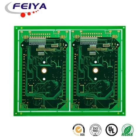
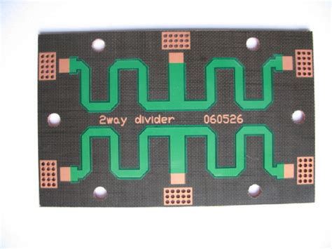
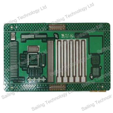
What is a Teflon PCB?
A Teflon PCB, also known as a PTFE (polytetrafluoroethylene) PCB, is a type of printed circuit board that uses Teflon as the base material instead of the more common FR-4 or other substrate materials. Teflon is a synthetic fluoropolymer known for its excellent dielectric properties, high temperature resistance, and chemical inertness.
Advantages of Teflon PCBs
Teflon PCBs offer several advantages over traditional PCB materials:
-
Low dielectric constant and dissipation factor: Teflon has a low dielectric constant (2.1) and dissipation factor (0.0002), which enables faster signal transmission and lower signal loss, making it ideal for high-frequency applications.
-
High temperature resistance: Teflon PCBs can withstand temperatures up to 260°C (500°F) continuously and even higher temperatures for short durations, making them suitable for harsh environments.
-
Chemical resistance: Teflon is highly resistant to most chemicals, including acids, bases, and solvents, ensuring the PCB’s reliability in chemically aggressive environments.
-
Low moisture absorption: Teflon has a very low moisture absorption rate (0.01%), which helps maintain the PCB’s electrical properties and dimensional stability in humid conditions.
-
Excellent mechanical properties: Teflon PCBs have a high tensile strength and flexural strength, making them durable and resistant to physical stress.
Applications of Teflon PCBs
Due to their unique properties, Teflon PCBs find applications in various industries:
-
High-frequency electronics: Teflon PCBs are widely used in RF and microwave applications, such as radar systems, satellite communication, and wireless infrastructure.
-
Aerospace and defense: The high temperature resistance and chemical inertness of Teflon PCBs make them suitable for aerospace and defense applications, including avionics, missile guidance systems, and space exploration.
-
Medical devices: Teflon’s biocompatibility and chemical resistance make it an ideal choice for medical devices, such as implantable devices, surgical instruments, and diagnostic equipment.
-
Industrial automation: Teflon PCBs can withstand harsh industrial environments, making them suitable for process control, monitoring systems, and power electronics in factories and plants.
-
Automotive electronics: The high temperature resistance of Teflon PCBs is beneficial for automotive applications, such as engine control units, sensors, and power management systems.
Teflon PCB Manufacturing Process
The manufacturing process for Teflon PCBs is similar to that of traditional PCBs, with a few key differences due to the unique properties of Teflon.
Material Selection
Teflon PCBs use PTFE laminates as the base material, which can be reinforced with glass fibers or ceramic fillers to improve mechanical strength and thermal conductivity. Common Teflon laminates include:
- Rogers RT/duroid
- Taconic TLY
- Arlon DiClad
- Isola IS680
The choice of laminate depends on the specific application requirements, such as frequency range, thermal management, and mechanical properties.
PCB Design Considerations
When designing a Teflon PCB, engineers must consider the following factors:
-
Thermal expansion: Teflon has a higher coefficient of thermal expansion (CTE) compared to traditional PCB materials, which can cause dimensional changes and stress on the board during temperature fluctuations. Designers must account for this by using appropriate layout techniques and component placement.
-
Drilling and routing: Teflon is a soft material, making it prone to deformation during drilling and routing processes. Special tools and settings are required to minimize damage and ensure precise hole and trace formation.
-
Adhesion: Teflon’s low surface energy can make it challenging to achieve strong adhesion between the copper traces and the substrate. Special surface treatments, such as plasma or chemical etching, may be necessary to improve adhesion.
-
Impedance control: Due to Teflon’s low dielectric constant, designers must carefully control the impedance of the PCB traces to ensure proper signal integrity and minimize reflections.
Fabrication Process
The fabrication process for Teflon PCBs involves the following steps:
-
Lamination: The Teflon laminate is bonded with copper foil using heat and pressure to create a copper-clad laminate.
-
Drilling: Holes for through-hole components and vias are drilled using specialized tools and settings to minimize deformation.
-
Patterning: The desired circuit pattern is transferred onto the copper layer using photolithography or laser direct imaging (LDI) techniques.
-
Etching: The unwanted copper is removed using a chemical etching process, leaving behind the desired circuit traces.
-
Surface finish: A surface finish, such as ENIG (Electroless Nickel Immersion Gold) or HASL (Hot Air Solder Leveling), is applied to protect the copper traces and improve solderability.
-
Solder mask and silkscreen: A solder mask is applied to protect the traces and prevent short circuits, while a silkscreen layer is added for component identification and labeling.
-
Routing and scoring: The PCB panel is routed and scored to create individual boards with the desired shape and size.
-
Testing and inspection: The finished Teflon PCBs undergo various tests and inspections to ensure they meet the required specifications and quality standards.

Teflon PCB Material Properties
Teflon possesses unique material properties that make it an ideal choice for high-performance PCB applications. The following table compares the key properties of Teflon with those of FR-4, a common PCB substrate material:
| Property | Teflon (PTFE) | FR-4 |
|---|---|---|
| Dielectric Constant (1 MHz) | 2.1 | 4.5 |
| Dissipation Factor (1 MHz) | 0.0002 | 0.02 |
| Thermal Conductivity (W/m·K) | 0.2 – 0.3 | 0.3 |
| CTE (ppm/°C) | 100 – 200 | 14 – 16 |
| Tensile Strength (MPa) | 20 – 35 | 415 |
| Flexural Strength (MPa) | 10 – 25 | 415 |
| Maximum Operating Temperature (°C) | 260 | 130 |
| Moisture Absorption (%) | 0.01 | 0.1 – 0.3 |
As evident from the table, Teflon has a lower dielectric constant and dissipation factor, enabling faster signal transmission and lower loss. However, it has a higher CTE and lower mechanical strength compared to FR-4, necessitating careful design considerations.

Teflon PCB Design Guidelines
To ensure optimal performance and reliability of Teflon PCBs, designers should follow these guidelines:
-
Thermal management: Use thermal vias, heat sinks, and other thermal management techniques to dissipate heat efficiently and minimize thermal stress on the board.
-
Controlled impedance: Carefully design the PCB traces to maintain consistent impedance and minimize signal reflections, especially for high-frequency applications.
-
Mechanical support: Use additional mechanical supports, such as stiffeners or brackets, to compensate for Teflon’s lower mechanical strength and prevent board warpage.
-
Hole and trace sizing: Use appropriate hole and trace sizes to minimize deformation during drilling and routing processes, and ensure adequate copper adhesion.
-
Surface treatment: Apply suitable surface treatments, such as plasma or chemical etching, to improve the adhesion between the copper traces and the Teflon substrate.
-
Component selection: Choose components that are compatible with Teflon’s thermal and mechanical properties, and use appropriate mounting techniques to minimize stress on the board.

Teflon PCB testing and Quality Control
To ensure the reliability and performance of Teflon PCBs, manufacturers employ various testing and quality control methods:
-
Electrical testing: Continuity, insulation resistance, and high-potential (hipot) tests are conducted to verify the electrical integrity of the PCB.
-
Impedance Testing: Time-domain reflectometry (TDR) or vector network analyzer (VNA) measurements are used to verify the impedance of the PCB traces and ensure proper signal integrity.
-
Environmental testing: Teflon PCBs are subjected to thermal cycling, humidity, and vibration tests to evaluate their performance under various environmental conditions.
-
Microsectioning: Cross-sections of the PCB are examined under a microscope to verify the quality of the plated through-holes, copper adhesion, and layer registration.
-
X-ray inspection: X-ray imaging is used to detect internal defects, such as voids, delamination, or misaligned components.
-
Automated optical inspection (AOI): AOI systems are employed to detect surface defects, such as solder bridging, component misalignment, or trace damage.
By implementing these testing and quality control measures, manufacturers can ensure that Teflon PCBs meet the required specifications and performance standards.
Frequently Asked Questions (FAQ)
-
Q: What is the main difference between Teflon PCBs and traditional FR-4 PCBs?
A: The main difference is the base material. Teflon PCBs use PTFE (polytetrafluoroethylene) as the substrate, while FR-4 PCBs use a glass-reinforced epoxy laminate. Teflon has a lower dielectric constant, lower dissipation factor, and higher temperature resistance compared to FR-4. -
Q: Are Teflon PCBs more expensive than FR-4 PCBs?
A: Yes, Teflon PCBs are generally more expensive than FR-4 PCBs due to the higher cost of PTFE laminates and the specialized manufacturing processes required. -
Q: Can Teflon PCBs be used for all applications?
A: While Teflon PCBs offer superior performance in high-frequency, high-temperature, and chemically harsh environments, they may not be necessary or cost-effective for all applications. FR-4 PCBs are still suitable for many general-purpose electronic applications. -
Q: How do I select the right Teflon laminate for my application?
A: The choice of Teflon laminate depends on factors such as the frequency range, thermal requirements, and mechanical properties needed for your specific application. Consult with your PCB manufacturer or material supplier to determine the most suitable Teflon laminate for your project. -
Q: Are there any special considerations for assembling components on Teflon PCBs?
A: Yes, the low surface energy of Teflon can make it challenging to achieve strong adhesion between the components and the substrate. Special surface treatments, such as plasma or chemical etching, may be necessary to improve adhesion. Additionally, the higher CTE of Teflon may require the use of flexible or low-stress component mounting techniques to minimize mechanical stress on the board.
Conclusion
Teflon PCBs offer unique advantages over traditional PCB materials, making them an ideal choice for high-performance applications in demanding environments. With their low dielectric constant, high temperature resistance, and chemical inertness, Teflon PCBs enable faster signal transmission, lower loss, and reliable operation in harsh conditions.
However, designing and manufacturing Teflon PCBs requires careful consideration of their unique properties and specialized processes. By following appropriate design guidelines, selecting compatible components, and implementing rigorous testing and quality control measures, engineers can ensure the optimal performance and reliability of Teflon PCBs in their applications.
As technology continues to advance, the demand for high-performance electronics in challenging environments will continue to grow. Teflon PCBs will play an increasingly important role in enabling these advancements across various industries, from aerospace and defense to medical devices and industrial automation.
By understanding the properties, advantages, and design considerations of Teflon PCBs, engineers can leverage this innovative material to push the boundaries of electronic performance and reliability in the most demanding applications.

No responses yet