Introduction to PCB Form Factors
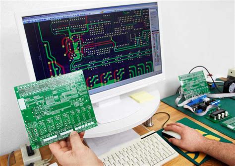
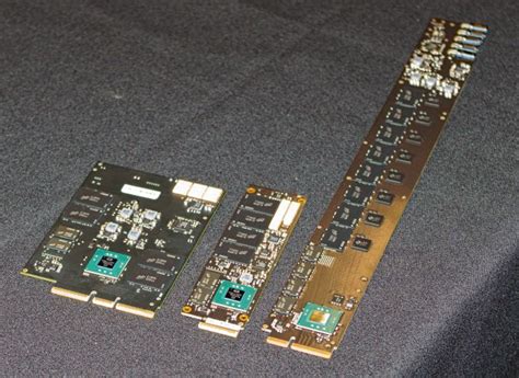
Printed Circuit Board (PCB) form factors refer to the physical dimensions, shape, and layout of a PCB. Choosing the right PCB form factor is crucial for ensuring compatibility, functionality, and efficiency in electronic devices. However, selecting the appropriate form factor can be a daunting task, especially for those new to PCB design. In this article, we will explore four key considerations that will help you take the fear out of choosing PCB form factors.
Understanding the Different Types of PCB Form Factors
Before diving into the considerations, let’s take a look at some common PCB form factors:
| Form Factor | Description | Typical Applications |
|---|---|---|
| ATX | Advanced Technology Extended, standard for desktop motherboards | Desktop computers |
| Mini-ITX | Compact form factor for small-sized motherboards | Small form factor PCs, embedded systems |
| PCIe | Peripheral Component Interconnect Express, used for expansion cards | Graphics cards, sound cards, SSDs |
| Arduino | Open-source platform for microcontroller boards | DIY projects, prototyping, education |
| Raspberry Pi | Single-board computer with a credit card-sized form factor | Education, hobbyist projects, embedded systems |
ATX Form Factor
The ATX form factor, introduced by Intel in 1995, has become the standard for desktop computer motherboards. It specifies the dimensions, mounting hole locations, and connector placements to ensure compatibility with standard computer cases and power supplies.
Key features of the ATX form factor:
– Motherboard dimensions: 305mm x 244mm (12″ x 9.6″)
– Mounting holes: 9 standoff mounting holes
– Power supply: 24-pin main power connector and 4-pin or 8-pin CPU power connector
– Expansion slots: Typically 7 slots for PCIe or PCI cards
Mini-ITX Form Factor
The Mini-ITX form factor, developed by VIA Technologies, is a compact motherboard design aimed at small form factor PCs and embedded systems. It offers a balance between performance and size, making it popular for home theater PCs (HTPCs), industrial applications, and space-constrained environments.
Key features of the Mini-ITX form factor:
– Motherboard dimensions: 170mm x 170mm (6.7″ x 6.7″)
– Mounting holes: 4 standoff mounting holes
– Power supply: 24-pin main power connector and 4-pin CPU power connector
– Expansion slots: Typically 1 slot for a PCIe card
PCIe Form Factor
PCIe (Peripheral Component Interconnect Express) is a high-speed serial bus standard used for connecting expansion cards to a motherboard. PCIe form factors define the physical dimensions and connector types for these expansion cards.
Common PCIe form factors include:
– Full-height, full-length (FHFL): 312mm x 107mm (12.283″ x 4.2″)
– Half-height, half-length (HHHL): 167.65mm x 68.9mm (6.6″ x 2.731″)
– M.2: Compact form factor for SSDs and Wi-Fi cards, with varying lengths (e.g., 2242, 2260, 2280)
Arduino Form Factor
Arduino is an open-source platform for microcontroller boards, popular among hobbyists, students, and professionals for its ease of use and versatility. Arduino boards come in various form factors, each with different features and capabilities.
Some popular Arduino form factors include:
– Arduino Uno: 68.6mm x 53.4mm (2.7″ x 2.1″), with USB, power jack, and headers for shields
– Arduino Nano: 45mm x 18mm (1.77″ x 0.7″), compact board with mini-USB and headers
– Arduino Mega: 101.6mm x 53.3mm (4″ x 2.1″), enhanced board with more memory and I/O pins
Raspberry Pi Form Factor
Raspberry Pi is a series of single-board computers developed by the Raspberry Pi Foundation. These credit card-sized devices are designed for education, hobbyist projects, and embedded applications. Raspberry Pi boards have a standardized form factor, with minor variations between models.
Key features of the Raspberry Pi form factor:
– Board dimensions: Approximately 85mm x 56mm (3.35″ x 2.2″)
– Mounting holes: 4 mounting holes in a rectangular pattern
– Connectors: USB, HDMI, Ethernet, GPIO pins, and others depending on the model

Four Key Considerations for Choosing PCB Form Factors
Now that we have a basic understanding of various PCB form factors let’s explore the four key considerations that will help you select the most appropriate one for your project.
1. Application and Functionality
The first and most crucial consideration when choosing a PCB form factor is the intended application and functionality of your device. Different form factors cater to specific needs and requirements, so it’s essential to align your choice with the purpose of your project.
For example, if you are designing a desktop computer motherboard, the ATX form factor would be the most suitable choice due to its standardized dimensions and compatibility with common computer cases and power supplies. On the other hand, if you are working on a compact embedded system, the Mini-ITX or even smaller form factors like the Raspberry Pi might be more appropriate to meet the size constraints and power requirements.
When evaluating your application and functionality needs, ask yourself the following questions:
– What is the primary purpose of my device?
– What are the space constraints for my PCB?
– What components and connectors do I need to accommodate?
– What are the power requirements for my device?
– Are there any industry standards or regulations I need to adhere to?
Answering these questions will help you narrow down your form factor options and ensure that your choice aligns with the goals and requirements of your project.
2. Compatibility and Interoperability
Compatibility and interoperability are essential factors to consider when selecting a PCB form factor. Your chosen form factor should be compatible with the components, connectors, and peripherals you plan to use in your device.
For instance, if you are designing a custom expansion card for a desktop computer, you would need to choose a PCIe form factor that matches the available slots on the motherboard. Similarly, if you are using a specific microcontroller or single-board computer, like an Arduino or Raspberry Pi, you should ensure that your PCB form factor is compatible with the pin layout and mounting hole pattern of the chosen platform.
To ensure compatibility and interoperability, consider the following:
– Check the specifications and datasheets of the components and connectors you plan to use
– Research the compatibility of your chosen form factor with industry standards and regulations
– Consider the availability and cost of compatible components and peripherals
– Test your design with the intended components and platforms to verify compatibility
By addressing compatibility and interoperability early in the design process, you can avoid potential issues down the line and ensure that your device functions as intended.
3. Scalability and Future-Proofing
When choosing a PCB form factor, it’s important to consider the scalability and future-proofing of your design. As technology advances and your project requirements evolve, you may need to update or expand your device’s capabilities. Selecting a form factor that allows for flexibility and growth can save you time and resources in the long run.
Consider the following aspects of scalability and future-proofing:
– Choose a form factor that offers sufficient space for additional components or features you may need in the future
– Opt for a form factor with a well-established ecosystem and community support to ensure access to resources and updates
– Consider the availability and longevity of compatible components and peripherals
– Design your PCB layout with modularity in mind, allowing for easy upgrades or modifications
By selecting a PCB form factor that supports scalability and future-proofing, you can create a device that adapts to changing requirements and remains relevant over time.
4. Cost and Availability
Finally, cost and availability are crucial factors to consider when choosing a PCB form factor. The price and accessibility of components, connectors, and peripherals can vary significantly depending on the chosen form factor, affecting your project’s overall budget and timeline.
When evaluating cost and availability, consider the following:
– Research the cost of components and peripherals compatible with your chosen form factor
– Compare prices from multiple suppliers to ensure you are getting the best value for your money
– Consider the availability and lead times of components, especially for specialized or niche form factors
– Factor in the cost of any additional tools, equipment, or services required for your chosen form factor (e.g., custom enclosures, specialized assembly)
By carefully assessing the cost and availability implications of your chosen PCB form factor, you can make informed decisions that align with your project’s budget and timeline constraints.

FAQ
1. What is the most common PCB form factor for desktop computers?
The most common PCB form factor for desktop computers is the ATX form factor. It provides a standardized layout for motherboards, ensuring compatibility with standard computer cases and power supplies.
2. Can I use a Raspberry Pi form factor for an industrial embedded application?
Yes, the Raspberry Pi form factor can be used for industrial embedded applications, provided it meets the specific requirements of your project, such as processing power, I/O capabilities, and environmental factors like temperature and vibration tolerance.
3. What is the difference between full-height and half-height PCIe form factors?
The main difference between full-height and half-height PCIe form factors is their physical dimensions. Full-height PCIe cards are taller and typically used in desktop computers, while half-height PCIe cards are shorter and more commonly used in small form factor or low-profile systems.
4. Are Arduino form factors compatible with each other?
Arduino form factors are generally not directly compatible with each other due to differences in pin layouts and board dimensions. However, many Arduino boards share similar architectures and programming interfaces, making it possible to port code between different form factors with minimal modifications.
5. How can I ensure compatibility between my chosen PCB form factor and the components I plan to use?
To ensure compatibility between your chosen PCB form factor and components, thoroughly review the specifications and datasheets of the components and connectors you plan to use. Look for information on pin layouts, mounting hole patterns, and physical dimensions to verify that they match your chosen form factor. Additionally, research any industry standards or regulations that may apply to your project to ensure compliance.

Conclusion
Choosing the right PCB form factor is a critical decision that can significantly impact the success of your electronic device project. By considering the four key factors discussed in this article – application and functionality, compatibility and interoperability, scalability and future-proofing, and cost and availability – you can take the fear out of selecting the most appropriate form factor for your needs.
Remember to align your choice with the specific requirements and constraints of your project, and thoroughly research and test your design to ensure compatibility and functionality. With careful consideration and planning, you can create a device that meets your goals and exceeds expectations.

No responses yet