Understanding PCB Measurement Units and Settings
When designing printed circuit boards (PCBs), it’s crucial to have the right measurement units and settings configured in your PCB design software. This ensures accuracy, consistency, and compatibility throughout the design process. In this article, we’ll dive into the world of PCB measurement preferences, focusing on how to switch the default unit and adjust other essential settings.
Common PCB Measurement Units
PCB design software typically supports various measurement units to cater to different design requirements and regional preferences. The most common units used in PCB design are:
| Unit | Description |
|---|---|
| mil | Thousandths of an inch (1 mil = 0.001 inch) |
| mm | Millimeters |
| inch | Inches |
| cm | Centimeters |
The choice of measurement unit depends on factors such as the PCB manufacturer’s specifications, the designer’s preference, and the industry standards in a particular region.
Importance of Consistent Measurement Units
Maintaining consistent measurement units throughout the PCB design process is essential for several reasons:
-
Accuracy: Using the same unit ensures that all measurements are accurate and consistent, reducing the risk of errors and discrepancies.
-
Communication: When collaborating with team members or communicating with manufacturers, using a consistent unit helps avoid confusion and misinterpretation.
-
Compatibility: Some PCB manufacturers have specific requirements for the measurement unit used in the design files. Adhering to their preferred unit ensures smooth communication and avoids any issues during manufacturing.
Switching the Default Measurement Unit
Most PCB design software allows you to change the default measurement unit according to your preferences. Here’s a general step-by-step guide on how to switch the default unit:
- Open your PCB design software.
- Navigate to the application settings or preferences menu. This is usually located in the main menu bar or under the “File” or “Edit” menu.
- Look for options related to “Units,” “Measurement Units,” or “Design Settings.”
- Select the desired default unit from the available options (e.g., mil, mm, inch).
- Save the changes and restart the software if required.
The exact steps may vary depending on the specific PCB design software you are using. Refer to the software’s documentation or user manual for detailed instructions.
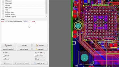
Example: Switching Default Unit in Altium Designer
Let’s take a look at how to change the default measurement unit in Altium Designer, a popular PCB design software:
- Open Altium Designer.
- Go to “DXP” in the main menu and select “Preferences.”
- In the Preferences window, navigate to the “PCB Editor” section on the left.
- Click on “General” under “PCB Editor.”
- Locate the “Default Units” option and select the desired unit from the dropdown menu (e.g., mil, mm, inch).
- Click “OK” to save the changes.
After following these steps, the default measurement unit in Altium Designer will be updated accordingly.

Other PCB Design Measurement Preferences
Apart from the default measurement unit, there are other measurement-related preferences you can customize in your PCB design software to suit your design requirements. Let’s explore a few common ones:
Grid Settings
The grid is a fundamental feature in PCB design software that helps align and position components accurately. You can adjust the grid settings to match your desired unit and precision. Here’s how to modify grid settings in most PCB design software:
- Open the application settings or preferences menu.
- Look for options related to “Grid,” “Snap Grid,” or “Grid Settings.”
- Adjust the grid size, spacing, and visibility as needed.
- Save the changes.
| Setting | Description |
|---|---|
| Grid Size | The size of each grid cell (e.g., 5 mil, 0.5 mm) |
| Grid Spacing | The distance between grid lines (e.g., 10 mil, 1 mm) |
| Grid Visibility | The visibility of the grid lines (e.g., always visible, visible when zoomed in) |
Customizing the grid settings allows you to work with a level of precision that suits your design requirements and helps maintain consistency in component placement and routing.
Dimension Settings
Dimension settings control how measurements are displayed on the PCB layout. You can customize the dimension units, precision, and formatting to ensure clarity and readability. Here’s how to access and modify dimension settings:
- Open the application settings or preferences menu.
- Look for options related to “Dimensions,” “Dimension Settings,” or “Annotation Settings.”
- Adjust the dimension units, precision, and formatting options as desired.
- Save the changes.
| Setting | Description |
|---|---|
| Dimension Units | The unit used for displaying dimensions (e.g., mil, mm, inch) |
| Precision | The number of decimal places displayed in dimensions |
| Formatting | Options for formatting dimensions (e.g., leading zeros, trailing zeros, separator) |
Customizing dimension settings helps create clear and accurate dimensions on your PCB layout, making it easier for manufacturers and assemblers to interpret the design.
Drill Hole Settings
Drill holes are an essential aspect of PCB design, as they allow components to be mounted and connected. You can customize drill hole settings to match your manufacturing requirements and ensure compatibility with your chosen PCB fabrication process. Here’s how to access and modify drill hole settings:
- Open the application settings or preferences menu.
- Look for options related to “Drill Holes,” “Hole Settings,” or “Pad Settings.”
- Adjust the drill hole units, sizes, and tolerances as needed.
- Save the changes.
| Setting | Description |
|---|---|
| Drill Hole Units | The unit used for specifying drill hole sizes (e.g., mil, mm, inch) |
| Drill Hole Sizes | The available drill hole sizes in the design library |
| Tolerances | The acceptable tolerance range for drill hole sizes |
Customizing drill hole settings ensures that your PCB design is manufacturable and meets the requirements of your chosen PCB fabrication process.

Best Practices for PCB Measurement Preferences
To optimize your PCB design workflow and ensure consistency and accuracy, consider the following best practices related to measurement preferences:
-
Consistency: Maintain consistent measurement units throughout your design process, from schematic capture to PCB layout and documentation.
-
Communication: Clearly communicate the measurement units used in your design when collaborating with team members, manufacturers, or clients to avoid confusion and errors.
-
Manufacturer Requirements: Consult with your PCB manufacturer to understand their preferred measurement units and settings. Adhering to their guidelines ensures smooth communication and minimizes the risk of manufacturing issues.
-
Documentation: Include the measurement units and any specific settings used in your design in the documentation or readme files accompanying your design files. This helps others understand and work with your design effectively.
-
Regular Review: Periodically review your measurement preferences and settings to ensure they align with your current design requirements and industry standards.
By following these best practices, you can streamline your PCB design process, improve accuracy, and enhance collaboration with stakeholders.

Frequently Asked Questions (FAQ)
-
Q: What is the most common measurement unit used in PCB design?
A: The most common measurement unit used in PCB design is mil (thousandths of an inch). However, the choice of unit can vary depending on regional preferences and specific industry requirements. -
Q: Can I use different measurement units for different aspects of my PCB design?
A: While it’s possible to use different measurement units for different aspects of your PCB design, it’s generally recommended to maintain consistency throughout the design process to avoid confusion and errors. -
Q: How do I know which measurement unit my PCB manufacturer prefers?
A: The best way to know your PCB manufacturer’s preferred measurement unit is to consult with them directly. Most manufacturers provide guidelines or specifications that outline their requirements, including the preferred unit of measurement. -
Q: What should I do if I receive design files from a colleague or client that use a different measurement unit than my preferred one?
A: If you receive design files with a different measurement unit, you can either convert the units to your preferred unit using your PCB design software’s built-in conversion tools or adjust your own software settings to match the received files. It’s important to communicate any changes made to the original designer to ensure clarity and consistency. -
Q: Can I change the measurement units used in my PCB design software’s library components?
A: Most PCB design software allows you to customize the measurement units used in library components. However, the process may vary depending on the specific software you are using. Refer to your software’s documentation or user manual for detailed instructions on how to modify library component settings.
Conclusion
Switching the default measurement unit and customizing other PCB design measurement preferences are essential steps in creating accurate, consistent, and manufacturable PCB designs. By understanding the available units, settings, and best practices, you can optimize your design workflow, improve communication with stakeholders, and ensure compatibility with manufacturing requirements.
Remember to regularly review and update your measurement preferences to align with your evolving design needs and industry standards. By staying proactive and adaptable, you can create high-quality PCB designs that meet your project goals and exceed expectations.
Happy PCB designing!

No responses yet