Introduction to PCB Noise Suppression
Printed Circuit Boards (PCBs) are essential components in modern electronic devices. However, PCBs are susceptible to various types of noise and electromagnetic interference (EMI) that can degrade the performance of the circuit and cause malfunctions. To ensure the proper functioning of electronic devices, it is crucial to suppress noise and EMI in PCBs through effective analog filter design.
In this article, we will dive into the world of PCB noise suppression, exploring the sources of noise and EMI, their effects on PCBs, and the techniques used to mitigate these issues. We will focus on analog filter design as a key method for suppressing noise and EMI in PCBs, discussing the different types of filters, their characteristics, and their applications.
Understanding Noise and EMI in PCBs
Sources of Noise and EMI
Noise and EMI in PCBs can originate from various sources, both internal and external to the circuit. Some common sources include:
- Power supply noise
- Digital switching noise
- Crosstalk between signal traces
- External electromagnetic interference (EMI)
- Thermal noise
Effects of Noise and EMI on PCBs
Noise and EMI can have detrimental effects on the performance of PCBs, leading to issues such as:
- Signal distortion
- Reduced signal-to-noise ratio (SNR)
- Increased bit error rates (BER)
- False triggering of digital circuits
- Electromagnetic compatibility (EMC) compliance issues
Analog Filter Design for PCB Noise Suppression
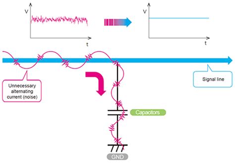
Analog filters are essential tools for suppressing noise and EMI in PCBs. By selectively attenuating unwanted frequencies while allowing desired signals to pass through, analog filters can effectively reduce the impact of noise and EMI on the circuit.
Types of Analog Filters
There are four main types of analog filters, each with its own characteristics and applications:
- Low-pass filters (LPF)
- High-pass filters (HPF)
- Band-pass filters (BPF)
- Band-stop filters (BSF)
Low-Pass Filters (LPF)
Low-pass filters allow low-frequency signals to pass through while attenuating high-frequency signals. They are commonly used to suppress high-frequency noise and EMI in PCBs.
| Filter Order | Roll-off Rate | Complexity |
|---|---|---|
| 1st order | -6 dB/octave | Low |
| 2nd order | -12 dB/octave | Moderate |
| 3rd order | -18 dB/octave | High |
| 4th order | -24 dB/octave | Very High |
High-Pass Filters (HPF)
High-pass filters allow high-frequency signals to pass through while attenuating low-frequency signals. They are useful for removing low-frequency noise, such as power supply ripple, from the signal path.
Band-Pass Filters (BPF)
Band-pass filters allow a specific range of frequencies to pass through while attenuating frequencies outside the passband. They are used to isolate desired signals from unwanted noise and interference.
Band-Stop Filters (BSF)
Band-stop filters, also known as notch filters, attenuate a specific range of frequencies while allowing frequencies outside the stopband to pass through. They are useful for eliminating specific sources of noise or interference, such as power line harmonics.
Filter Characteristics
When designing analog filters for PCB noise suppression, several key characteristics must be considered:
- Cutoff frequency (fc)
- Filter order
- Passband ripple
- Stopband attenuation
- Phase response
The cutoff frequency determines the boundary between the passband and the stopband, while the filter order affects the steepness of the transition between the two. Passband ripple and stopband attenuation determine the filter’s ability to suppress unwanted frequencies, and the phase response is crucial for maintaining signal integrity.
Filter Implementation
Analog filters can be implemented using various circuit topologies, such as:
- Passive filters (RC, RL, LC)
- Active filters (op-amp based)
- Switched-capacitor filters
- Integrated filter solutions (e.g., SAW filters)
The choice of filter topology depends on factors such as the desired filter characteristics, the available board space, power consumption, and cost.

PCB Layout Considerations for Noise Suppression
In addition to analog filter design, proper PCB layout is essential for effective noise suppression. Some key layout considerations include:
- Proper grounding and power supply decoupling
- Minimizing signal trace lengths and loop areas
- Separating sensitive analog and digital sections
- Using ground planes and shielding techniques
- Following EMC design guidelines
By adhering to best practices in PCB layout, designers can minimize the impact of noise and EMI on the circuit, complementing the effects of analog filtering.
Case Studies and Applications
To illustrate the practical application of analog filter design for PCB noise suppression, let’s explore a few case studies:
Case Study 1: Suppressing Power Supply Noise in a High-Speed ADC
In this case study, a high-speed analog-to-digital converter (ADC) was experiencing performance degradation due to power supply noise. By implementing a low-pass filter with a cutoff frequency of 10 kHz on the ADC’s power supply line, the noise was effectively suppressed, resulting in a significant improvement in the ADC’s signal-to-noise ratio (SNR) and overall performance.
Case Study 2: Mitigating EMI in a Wireless Communication System
A wireless communication system was suffering from electromagnetic interference (EMI) caused by nearby electronic devices. By incorporating a band-stop filter tuned to the interfering frequency in the receiver’s front-end, the EMI was effectively mitigated, leading to improved signal quality and reduced bit error rates (BER).
Frequently Asked Questions (FAQ)
- What is the difference between passive and active filters?
Passive filters consist of passive components such as resistors, capacitors, and inductors, and do not require an external power source. Active filters, on the other hand, use active components like op-amps and require a power supply to function. Active filters offer more design flexibility and can achieve higher filter orders with fewer components compared to passive filters. - How do I select the appropriate cutoff frequency for my filter?
The choice of cutoff frequency depends on the specific noise and EMI characteristics of your PCB and the desired signal bandwidth. To determine the appropriate cutoff frequency, analyze the frequency spectrum of the noise and interference sources and choose a cutoff frequency that effectively separates the desired signal from the unwanted noise. - Can I use multiple filters in series to achieve better noise suppression?
Yes, using multiple filters in series, known as cascading, can provide improved noise suppression. By cascading filters with different cutoff frequencies and filter orders, you can achieve a steeper roll-off and better attenuation of unwanted frequencies. However, keep in mind that cascading filters also increases the overall circuit complexity and may introduce additional signal attenuation and phase shift. - What are some common pitfalls to avoid when designing analog filters for PCB noise suppression?
Some common pitfalls to avoid include: - Underestimating the importance of filter component selection and tolerance
- Neglecting the impact of filter impedance on the signal path
- Failing to consider the filter’s effect on signal integrity and phase response
- Overlooking the need for proper PCB layout and grounding practices
To avoid these pitfalls, carefully select filter components, consider the filter’s impact on the signal path, and follow best practices in PCB layout and grounding. - How can I verify the effectiveness of my analog filter design?
To verify the effectiveness of your analog filter design, you can use various tools and techniques, such as: - SPICE simulations to predict filter performance and identify potential issues
- Frequency response measurements using a network analyzer or spectrum analyzer
- Time-domain measurements using an oscilloscope to assess signal integrity and noise reduction
- EMC testing to ensure compliance with relevant standards and regulations
By employing these verification methods, you can validate your filter design and make necessary adjustments to optimize its performance.
Conclusion
Effective PCB noise suppression is crucial for ensuring the proper functioning and reliability of electronic devices. Analog filter design plays a key role in mitigating noise and EMI in PCBs, offering a wide range of filter types and characteristics to suit various application requirements.
By understanding the sources and effects of noise and EMI, selecting the appropriate filter topology, and following best practices in PCB layout, designers can successfully suppress unwanted frequencies and improve the overall performance of their circuits.
As electronic devices continue to evolve and become more complex, the importance of effective PCB noise suppression will only grow. By staying up-to-date with the latest techniques and technologies in analog filter design, engineers can tackle the challenges of noise and EMI head-on, paving the way for more reliable, high-performance electronic systems.
No responses yet