Introduction to Stub Transmission Lines
Stub transmission lines are a crucial component in the world of electrical engineering and telecommunications. These specialized transmission lines play a vital role in impedance matching, filtering, and signal conditioning. In this comprehensive article, we will delve into the fundamentals of stub transmission lines, exploring their functions, types, and applications. Additionally, we will discuss the importance of maintaining stub transmission lines and provide practical tips on how to keep them functioning optimally.
What are Stub Transmission Lines?
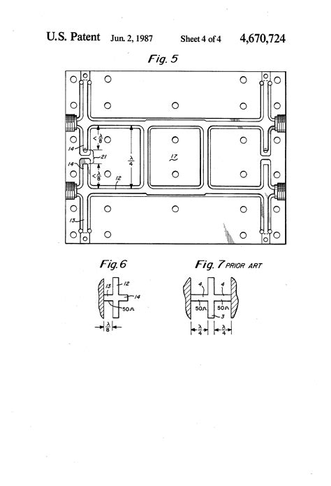
A stub transmission line is a short segment of transmission line that is connected in parallel or series with the main transmission line. The primary purpose of a stub transmission line is to introduce a specific impedance or reactance at a particular point along the main transmission line. By carefully selecting the length and characteristic impedance of the stub, engineers can achieve various effects, such as impedance matching, filtering, and phase shifting.
Stub transmission lines are commonly used in high-frequency applications, such as radio frequency (RF) circuits, microwave systems, and antenna design. They are essential for ensuring efficient power transfer, reducing signal reflections, and improving overall system performance.
Types of Stub Transmission Lines
There are three main types of stub transmission lines:
-
Open-Circuit Stub: An open-circuit stub is a transmission line segment that is left open at one end. It acts as a parallel reactance and introduces a capacitive or inductive effect, depending on its length relative to the wavelength of the signal.
-
Short-Circuit Stub: A short-circuit stub is a transmission line segment that is terminated with a short circuit (a direct connection to ground). It acts as a series reactance and introduces an inductive or capacitive effect, depending on its length relative to the wavelength of the signal.
-
Lumped-Element Stub: A lumped-element stub is a discrete component, such as a capacitor or inductor, that is used to approximate the behavior of a distributed stub transmission line. Lumped-element stubs are often employed in lower-frequency applications where the physical size of a distributed stub would be impractical.
| Type of Stub | Termination | Effect |
|---|---|---|
| Open-Circuit Stub | Open at one end | Parallel reactance (capacitive or inductive) |
| Short-Circuit Stub | Short-circuited at one end | Series reactance (inductive or capacitive) |
| Lumped-Element Stub | Discrete component (capacitor or inductor) | Approximates behavior of distributed stub |

Functions of Stub Transmission Lines
Stub transmission lines serve several important functions in electrical and telecommunications systems:
Impedance Matching
One of the primary functions of stub transmission lines is impedance matching. When two devices or components with different impedances are connected, a portion of the signal power is reflected back to the source, leading to inefficient power transfer and potential signal distortion. By using a stub transmission line of appropriate length and characteristic impedance, engineers can create an impedance transformer that matches the impedances of the source and load, minimizing reflections and ensuring maximum power transfer.
Filtering
Stub transmission lines can also act as filters, selectively attenuating or passing signals based on their frequency. By designing a stub with a specific length and termination, engineers can create various types of filters, such as low-pass, high-pass, band-pass, or band-stop filters. These filters are crucial for eliminating unwanted frequencies, reducing noise, and improving signal quality.
Phase Shifting
Another function of stub transmission lines is phase shifting. By adjusting the length of the stub relative to the wavelength of the signal, engineers can introduce a controlled phase shift in the transmission line. This capability is valuable in applications such as phased array antennas, where precise control over the phase of the signal is necessary for beam steering and directional control.
Harmonic Suppression
Stub transmission lines can be employed for harmonic suppression, which is the process of attenuating or eliminating unwanted harmonics generated by nonlinear devices, such as amplifiers or mixers. By placing a stub transmission line at a specific location along the main transmission line, engineers can create a notch filter that selectively attenuates the unwanted harmonic frequencies, improving the spectral purity of the signal.

Applications of Stub Transmission Lines
Stub transmission lines find applications in various fields, including:
-
RF and Microwave Circuits: Stub transmission lines are extensively used in RF and microwave circuits for impedance matching, filtering, and phase shifting. They are essential components in power amplifiers, low-noise amplifiers, mixers, and other high-frequency devices.
-
Antenna Design: Stub transmission lines play a crucial role in antenna design, particularly in matching the impedance of the antenna to the feed line. They are also used in phased array antennas for beam steering and directional control.
-
Telecommunications: In telecommunications systems, stub transmission lines are employed for impedance matching, filtering, and conditioning signals. They are used in base stations, repeaters, and other communication equipment to ensure efficient signal transmission and reception.
-
Test and Measurement: Stub transmission lines are utilized in test and measurement equipment, such as vector network analyzers and spectrum analyzers, for calibration and impedance matching purposes.

Maintaining Stub Transmission Lines
To ensure optimal performance and reliability, it is essential to maintain stub transmission lines properly. Here are some tips on how to keep stub transmission lines functioning effectively:
Regular Inspection
Regularly inspect stub transmission lines for any signs of damage, corrosion, or degradation. Look for physical defects, such as cracks, bends, or loose connections, which can affect the performance of the stub. Use visual inspection techniques and, if necessary, employ specialized tools like time-domain reflectometers (TDRs) to detect any anomalies.
Proper Termination
Ensure that stub transmission lines are properly terminated according to their intended design. Improper termination can lead to unwanted reflections, standing waves, and performance degradation. Use high-quality connectors and terminations that are rated for the specific frequency range and power levels of the application.
Environmental Protection
Protect stub transmission lines from environmental factors that can cause damage or deterioration. Shield them from excessive heat, moisture, and vibration. In outdoor installations, use weatherproof enclosures and protective coatings to prevent corrosion and exposure to the elements.
Impedance Monitoring
Regularly monitor the impedance of stub transmission lines to ensure they are functioning as designed. Use impedance measurement techniques, such as vector network analysis or time-domain reflectometry, to detect any changes in impedance that may indicate a fault or degradation in the stub.
Proper Handling and Installation
Handle and install stub transmission lines with care to avoid physical damage or stress. Follow the manufacturer’s guidelines for bending radius, torque specifications, and installation procedures. Use appropriate tools and techniques to minimize the risk of damage during installation or maintenance.
Regular Maintenance and Calibration
Perform regular maintenance and calibration of stub transmission lines to ensure they continue to meet the required specifications. Follow the recommended maintenance schedules and calibration procedures provided by the manufacturer. Keep accurate records of maintenance activities and any performance issues encountered.
Frequently Asked Questions (FAQ)
-
What is the difference between an open-circuit stub and a short-circuit stub?
An open-circuit stub is a transmission line segment that is left open at one end, acting as a parallel reactance. It introduces a capacitive or inductive effect, depending on its length relative to the wavelength of the signal. On the other hand, a short-circuit stub is terminated with a short circuit (direct connection to ground) and acts as a series reactance, introducing an inductive or capacitive effect based on its length. -
How do I determine the appropriate length of a stub transmission line for impedance matching?
The appropriate length of a stub transmission line for impedance matching depends on the wavelength of the signal and the desired impedance transformation. It is typically calculated using formulas based on transmission line theory, taking into account the characteristic impedance of the main transmission line and the desired matching impedance. Specialized software tools and calculators are available to assist in determining the optimal stub length. -
Can stub transmission lines be used for multiple frequency bands?
Yes, stub transmission lines can be designed to work effectively across multiple frequency bands. This is achieved by using multi-band stub designs, such as dual-band or tri-band stubs, which incorporate multiple stub segments of different lengths to provide the desired impedance matching or filtering characteristics at each frequency band of interest. -
What are the common materials used for constructing stub transmission lines?
Stub transmission lines are commonly constructed using materials that have good electrical conductivity and low loss at the operating frequencies. Some common materials include copper, aluminum, and brass. The choice of material depends on factors such as the frequency range, power handling requirements, and environmental conditions. In some cases, stub transmission lines may also employ dielectric materials, such as polytetrafluoroethylene (PTFE) or ceramic, for insulation and support. -
How often should stub transmission lines be inspected and maintained?
The frequency of inspection and maintenance for stub transmission lines depends on the specific application, operating conditions, and manufacturer’s recommendations. In general, it is advisable to perform regular visual inspections at least once every few months to check for any physical damage, corrosion, or degradation. More comprehensive maintenance, including impedance monitoring and calibration, should be conducted annually or as specified by the manufacturer. In critical applications or harsh environments, more frequent inspections and maintenance may be necessary to ensure optimal performance and reliability.
Conclusion
Stub transmission lines are essential components in electrical and telecommunications systems, providing crucial functions such as impedance matching, filtering, phase shifting, and harmonic suppression. By understanding the types, functions, and applications of stub transmission lines, engineers can design and optimize high-frequency circuits and systems for maximum performance and efficiency.
To keep stub transmission lines functioning effectively, regular inspection, proper termination, environmental protection, impedance monitoring, careful handling and installation, and regular maintenance and calibration are essential. By following these best practices, engineers can ensure the long-term reliability and optimal performance of stub transmission lines in various applications.
As technology continues to advance and the demand for high-frequency systems grows, the importance of stub transmission lines will only increase. By staying informed about the latest developments and techniques in stub transmission line design and maintenance, engineers can stay ahead of the curve and deliver cutting-edge solutions for a wide range of industries and applications.

No responses yet