Introduction to SOSA and Its Importance for PCB Design
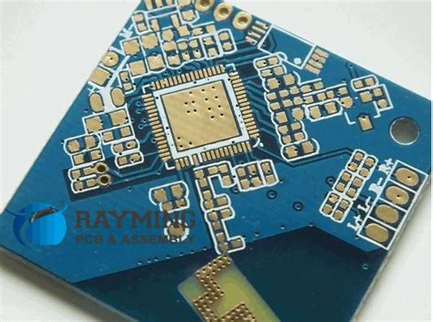
The Sensor Open Systems Architecture (SOSA) is a technical standard that aims to promote interoperability, modularity, and reusability in sensor systems across various platforms and domains. SOSA is particularly relevant for printed circuit board (PCB) designers, as it provides guidelines and specifications for designing boards that adhere to the standard’s requirements. By following the SOSA standard, PCB designers can create systems that are more easily integrated, maintained, and upgraded, leading to cost savings and improved performance.
Key Benefits of Adopting the SOSA Standard in PCB Design
- Interoperability: SOSA-compliant PCBs can be easily integrated with other SOSA-compliant components and systems, reducing integration challenges and costs.
- Modularity: The standard promotes a modular approach to PCB design, allowing for easier upgrades and maintenance of individual components without affecting the entire system.
- Reusability: SOSA-compliant PCBs can be reused across different platforms and domains, reducing development time and costs.
- Improved performance: By adhering to the standard’s guidelines, PCB designers can create systems with improved reliability, scalability, and overall performance.
SOSA Technical Standard: Key Aspects for PCB Designers
OpenVPX and MORA: The Foundation of SOSA
The SOSA standard builds upon the OpenVPX and Modular Open RF Architecture (MORA) standards, which provide a framework for designing modular, open-architecture systems. PCB designers should be familiar with these standards and their implications for board design.
OpenVPX (VITA 65)
OpenVPX is an open standard that defines the mechanical, electrical, and thermal interfaces for modular, high-performance computing systems. It is based on the VPX (VITA 46) standard and provides additional specifications for interoperability and modularity.
Key aspects of OpenVPX for PCB designers:
– Backplane and module form factors
– Connector types and pinouts
– Power supply requirements
– Cooling and thermal management
MORA (VITA 49.2)
MORA is an open standard that defines the interfaces and protocols for modular, open-architecture RF systems. It aims to promote interoperability and reusability of RF components across different platforms.
Key aspects of MORA for PCB designers:
– RF module form factors and interfaces
– Signal integrity and electromagnetic compatibility (EMC) requirements
– Power and control interfaces
– Thermal management considerations
SOSA Profiles and Their Impact on PCB Design
SOSA defines a set of profiles that specify the requirements for different types of sensor systems. These profiles cover various aspects, such as mechanical, electrical, and software interfaces, as well as performance and environmental requirements. PCB designers must understand the relevant profiles and their implications for board design.
Example SOSA Profiles
| Profile | Description | Key Requirements for PCB Design |
|---|---|---|
| General-Purpose Processor (GPP) | Defines requirements for general-purpose computing modules | – Form factor and dimensions – Power supply and consumption – Thermal management – Connector types and pinouts |
| Electro-Optical/Infrared (EO/IR) Sensor | Defines requirements for EO/IR sensor modules | – Form factor and dimensions – Signal integrity and EMC – Power supply and consumption – Thermal management – Optical interface requirements |
| Radar Sensor | Defines requirements for radar sensor modules | – Form factor and dimensions – Signal integrity and EMC – Power supply and consumption – Thermal management – RF interface requirements |
SOSA Conformance and Certification Process
To ensure that PCBs meet the SOSA standard’s requirements, designers must follow the conformance and certification process outlined by the SOSA Consortium. This process involves several steps, including:
- Self-assessment: Designers review their PCB designs against the relevant SOSA profiles and requirements.
- Third-party testing: Independent laboratories conduct tests to verify the PCB’s compliance with the standard.
- Certification: The SOSA Consortium reviews the test results and grants certification to compliant PCBs.
PCB designers should be familiar with the conformance and certification process and plan their design and testing activities accordingly.

Best Practices for Designing SOSA-Compliant PCBs
Signal Integrity and EMC Considerations
Signal integrity and electromagnetic compatibility (EMC) are critical aspects of SOSA-compliant PCB design. Designers must ensure that their boards meet the standard’s requirements for signal quality, crosstalk, and emissions.
Best practices for signal integrity and EMC:
– Use controlled impedance traces and terminations
– Minimize crosstalk through proper routing and layer stackup
– Implement appropriate grounding and shielding techniques
– Conduct signal integrity simulations and EMC testing
Thermal Management Strategies
Thermal management is essential for ensuring the reliability and performance of SOSA-compliant PCBs. Designers must consider the thermal requirements of the relevant SOSA profiles and implement appropriate cooling strategies.
Best practices for thermal management:
– Use thermal vias and planes to dissipate heat
– Select components with suitable thermal characteristics
– Implement heatsinks and other cooling solutions as needed
– Conduct thermal simulations and testing
Power Management and Distribution
Proper power management and distribution are critical for SOSA-compliant PCBs. Designers must ensure that their boards meet the standard’s requirements for power supply, consumption, and quality.
Best practices for power management and distribution:
– Use appropriate voltage regulators and converters
– Implement power sequencing and monitoring
– Minimize power supply noise and ripple
– Conduct power integrity simulations and testing
Mechanical Design Considerations
SOSA-compliant PCBs must meet the standard’s mechanical requirements, such as form factors, dimensions, and connector types. Designers should be familiar with these requirements and design their boards accordingly.
Best practices for mechanical design:
– Follow the relevant SOSA profile’s form factor and dimension specifications
– Use the specified connector types and pinouts
– Ensure proper mounting and fastening of components
– Conduct mechanical stress and vibration testing

Case Studies: Successful Implementation of SOSA in PCB Design
Case Study 1: Modular Radar Sensor PCB
- Objective: Design a modular radar sensor PCB that adheres to the SOSA standard’s requirements.
- Key challenges: Signal integrity, thermal management, and mechanical design.
- Solution: The PCB was designed using controlled impedance traces, appropriate grounding and shielding techniques, and thermal management strategies such as thermal vias and heatsinks. The mechanical design followed the relevant SOSA profile’s form factor and connector specifications.
- Results: The radar sensor PCB successfully passed the SOSA conformance and certification process, demonstrating improved interoperability and modularity.
Case Study 2: High-Performance Computing PCB
- Objective: Design a high-performance computing PCB that meets the SOSA standard’s requirements for general-purpose processors.
- Key challenges: Power management, thermal management, and signal integrity.
- Solution: The PCB was designed using appropriate voltage regulators and power sequencing techniques, thermal management strategies such as thermal planes and heatsinks, and signal integrity best practices such as controlled impedance traces and proper routing.
- Results: The high-performance computing PCB achieved SOSA certification, enabling its use across various platforms and domains, leading to cost savings and improved performance.

Frequently Asked Questions (FAQ)
-
Q: What is the difference between SOSA and OpenVPX?
A: SOSA is a technical standard that builds upon the OpenVPX standard, providing additional specifications and requirements for sensor systems. OpenVPX focuses on the mechanical, electrical, and thermal interfaces for modular, high-performance computing systems, while SOSA extends these concepts to sensor systems and incorporates other standards such as MORA. -
Q: Do all PCBs designed for sensor systems need to be SOSA-compliant?
A: While SOSA compliance is not mandatory for all sensor system PCBs, adhering to the standard offers several benefits, such as improved interoperability, modularity, and reusability. SOSA-compliant PCBs can be more easily integrated with other SOSA-compliant components and systems, reducing development time and costs. -
Q: What are the key aspects of SOSA that PCB designers should focus on?
A: PCB designers should focus on several key aspects of the SOSA standard, including: - Understanding the relevant SOSA profiles and their requirements
- Ensuring signal integrity and EMC compliance
- Implementing appropriate thermal management strategies
- Designing for proper power management and distribution
-
Meeting the standard’s mechanical requirements, such as form factors and connector types
-
Q: How can PCB designers ensure their boards are SOSA-compliant?
A: To ensure SOSA compliance, PCB designers should: - Review their designs against the relevant SOSA profiles and requirements
- Follow best practices for signal integrity, EMC, thermal management, power management, and mechanical design
- Conduct simulations and testing to verify compliance
-
Participate in the SOSA conformance and certification process, which involves self-assessment, third-party testing, and certification by the SOSA Consortium
-
Q: What are the benefits of designing SOSA-compliant PCBs?
A: Designing SOSA-compliant PCBs offers several benefits, including: - Improved interoperability and modularity, enabling easier integration with other SOSA-compliant components and systems
- Increased reusability across different platforms and domains, reducing development time and costs
- Enhanced reliability, scalability, and overall performance due to adherence to the standard’s guidelines and best practices
- Potential for cost savings through reduced integration challenges and improved maintainability
Conclusion
The SOSA standard is an essential consideration for PCB designers working on sensor systems. By understanding the key aspects of the standard, such as its foundation in OpenVPX and MORA, the relevance of SOSA profiles, and the conformance and certification process, designers can create PCBs that are more interoperable, modular, and reusable.
Implementing best practices for signal integrity, EMC, thermal management, power management, and mechanical design is crucial for designing SOSA-compliant PCBs. Case studies demonstrate the successful implementation of SOSA in PCB design, highlighting the benefits of improved interoperability, modularity, and performance.
As the demand for open-architecture, modular sensor systems continues to grow, PCB designers who are well-versed in the SOSA standard will be well-positioned to create boards that meet the evolving needs of the industry. By embracing SOSA and its principles, designers can contribute to the development of more efficient, cost-effective, and high-performance sensor systems.

No responses yet