What are SMD Components?
SMD components are electronic components that are designed to be mounted directly onto the surface of a printed circuit board (PCB). Unlike through-hole components, which have leads that are inserted into holes drilled in the PCB, SMD components have small metal pads or leads that are soldered directly onto the PCB’s surface. This allows for a more compact design and higher component density, as well as improved performance and reliability.
SMD components come in various shapes, sizes, and packages, depending on their function and application. Some common types of SMD components include:
- Resistors
- Capacitors
- Inductors
- Diodes
- Transistors
- Integrated Circuits (ICs)
SMD Component Packages
SMD components are available in a wide range of packages, each with its own set of dimensions, pin configurations, and marking conventions. Understanding these package types is essential for identifying and working with SMD components.
Chip Components
Chip components are the simplest and most common type of SMD component. They are small, rectangular components with two terminal pads on opposite sides. Chip components are used for resistors, capacitors, and inductors.
The size of a chip component is indicated by a four-digit code, where the first two digits represent the length, and the last two digits represent the width, in hundredths of an inch. For example, a “0805” chip component measures 0.08 inches (2.0 mm) by 0.05 inches (1.3 mm).
| Package Code | Length (mm) | Width (mm) | Height (mm) |
|---|---|---|---|
| 0201 | 0.6 | 0.3 | 0.3 |
| 0402 | 1.0 | 0.5 | 0.5 |
| 0603 | 1.6 | 0.8 | 0.8 |
| 0805 | 2.0 | 1.3 | 1.3 |
| 1206 | 3.2 | 1.6 | 1.6 |
SOT and SOD Packages
Small Outline Transistor (SOT) and Small Outline Diode (SOD) packages are used for discrete semiconductors, such as transistors and diodes. These packages have a small, rectangular body with leads extending from the sides.
Some common SOT and SOD packages include:
- SOT-23: A three-lead package commonly used for small-signal transistors and diodes.
- SOT-223: A four-lead package with a large thermal pad, used for power transistors and voltage regulators.
- SOD-123: A two-lead package used for small-signal and Schottky diodes.
QFP and QFN Packages
Quad Flat Pack (QFP) and Quad Flat No-lead (QFN) packages are used for integrated circuits (ICs) with a moderate to high pin count. QFP packages have leads extending from all four sides of the component, while QFN packages have pads on the underside of the component body.
QFP packages are designated by the number of pins and the pitch (spacing) between the pins. For example, a “TQFP-44” package has 44 pins with a 0.8 mm pitch.
QFN packages are designated by the number of pins and the size of the component body. For example, a “QFN-32-5×5” package has 32 pins and measures 5 mm by 5 mm.
BGA Packages
Ball Grid Array (BGA) packages are used for high-density ICs with a large number of interconnects. BGA components have an array of solder balls on the underside of the component body, which are used to connect the component to the PCB.
BGA packages are designated by the number of balls and the pitch between the balls. For example, a “BGA-256-1.0” package has 256 balls with a 1.0 mm pitch.
Identifying SMD Components
Identifying SMD components can be challenging due to their small size and the variety of package types and marking conventions. However, there are several methods and tools that can be used to identify SMD components.
Visual Inspection
The first step in identifying an SMD component is to visually inspect the component and its markings. Most SMD components have a code printed on their surface that indicates the component type, value, and tolerance. However, these codes can be difficult to read due to the small size of the components and the various marking conventions used by different manufacturers.
Some common marking conventions for SMD components include:
- Resistors: Resistor values are typically indicated by a three- or four-digit code, where the first two or three digits represent the significant figures, and the last digit represents the multiplier (number of zeros). For example, a resistor marked “473” has a value of 47 × 10³ ohms, or 47 kΩ.
- Capacitors: Capacitor values are often indicated by a three-digit code, where the first two digits represent the significant figures, and the third digit represents the multiplier. The capacitance is given in picofarads (pF). For example, a capacitor marked “104” has a value of 10 × 10⁴ pF, or 0.1 µF.
- Inductors: Inductor values are typically indicated by a code similar to that used for resistors, with the value given in microhenries (µH) or nanohenries (nH).
- Diodes: Diode markings usually consist of a two- or three-digit code that identifies the diode type and its characteristics, such as the forward voltage drop and maximum current rating.
- Transistors: Transistor markings often include a two- or three-character code that identifies the transistor type (e.g., “2N” for bipolar transistors, “BS” for SMD transistors) and a three- or four-digit number that identifies the specific transistor model.
- ICs: IC markings typically include the manufacturer’s logo, the device type or function, and a part number that identifies the specific IC model.
SMD Code Books and Online Resources
To aid in the identification of SMD components, many manufacturers provide code books or online resources that list the various component codes and their corresponding values or characteristics. These resources can be invaluable when working with unfamiliar or poorly marked components.
Some popular online resources for SMD component identification include:
- SMD Codebook: A comprehensive database of SMD component codes and their values or characteristics.
- Digi-Key Electronics: An electronic component distributor that provides datasheets and other technical information for a wide range of SMD components.
- Mouser Electronics: Another electronic component distributor with a vast library of datasheets and technical resources.
Multimeters and Component Testers
In some cases, visual inspection and reference materials may not be sufficient to positively identify an SMD component. In these situations, a multimeter or dedicated component tester can be used to measure the component’s electrical characteristics and determine its type and value.
Multimeters can be used to measure resistance, capacitance, and diode forward voltage drop, which can help identify resistors, capacitors, and diodes, respectively. However, multimeters may not be suitable for measuring small-value components or for identifying more complex components, such as transistors and ICs.
Component testers, such as the LCR-T4 ESR Meter, are specifically designed to measure and identify a wide range of SMD components, including resistors, capacitors, inductors, transistors, and diodes. These testers typically have a socket or test leads that can accommodate various SMD package types and provide a readout of the component’s type, value, and other characteristics.

Common SMD Component Types and Their Characteristics
Now that we have covered the basics of SMD component packages and identification methods, let’s take a closer look at some of the most common types of SMD components and their characteristics.
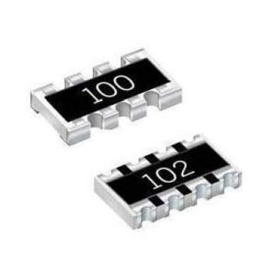
SMD Resistors
SMD resistors are passive components that resist the flow of electrical current. They are used to control voltage levels, limit current, and provide Impedance Matching in electronic circuits. SMD resistors are available in various package sizes, with 0402, 0603, and 0805 being the most common.
SMD resistors are typically marked with a three- or four-digit code that indicates the resistance value and tolerance. The first two or three digits represent the significant figures, and the last digit represents the multiplier. The tolerance is indicated by a letter code, with “F” denoting ±1%, “J” denoting ±5%, and “K” denoting ±10%.
For example, an SMD resistor marked “473J” has a value of 47 × 10³ ohms (47 kΩ) with a tolerance of ±5%.
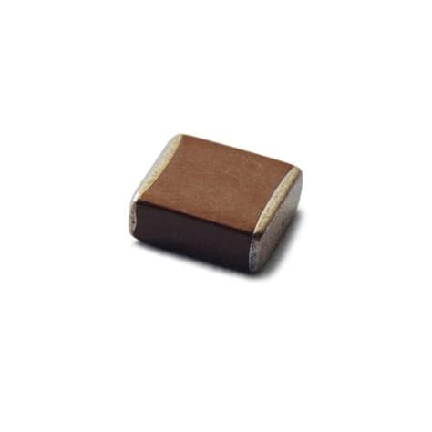
SMD Capacitors
SMD capacitors are passive components that store electrical energy in an electric field. They are used for filtering, decoupling, and energy storage in electronic circuits. SMD capacitors are available in various package sizes and dielectric materials, including ceramic, tantalum, and aluminum electrolytic.
Ceramic SMD capacitors are the most common type and are typically marked with a three-digit code that indicates the capacitance value in picofarads (pF). The first two digits represent the significant figures, and the third digit represents the multiplier.
For example, an SMD ceramic capacitor marked “104” has a value of 10 × 10⁴ pF, or 0.1 µF.
Tantalum and aluminum electrolytic SMD capacitors are often marked with their capacitance value and voltage rating in plain text, such as “10µF 16V”.
SMD Inductors
SMD inductors are passive components that store energy in a magnetic field. They are used for filtering, impedance matching, and energy storage in electronic circuits. SMD inductors are available in various package sizes and core materials, including ceramic, ferrite, and metal alloys.
SMD inductors are typically marked with a code similar to that used for resistors, with the value given in microhenries (µH) or nanohenries (nH). The first two or three digits represent the significant figures, and the last digit represents the multiplier.
For example, an SMD inductor marked “472” has a value of 47 × 10² nH, or 4.7 µH.
SMD Diodes
SMD diodes are semiconductor components that allow current to flow in only one direction. They are used for rectification, voltage regulation, and protection against reverse voltage in electronic circuits. Common types of SMD diodes include signal diodes, Schottky diodes, and Zener Diodes.
SMD diodes are usually marked with a two- or three-digit code that identifies the diode type and its characteristics, such as the forward voltage drop and maximum current rating. Some common SMD diode markings include:
- “1N4148”: A popular small-signal diode with a forward voltage drop of 0.7 V and a maximum current rating of 200 mA.
- “BAT54”: A Schottky diode with a low forward voltage drop of 0.3 V and a maximum current rating of 200 mA.
- “BZX84C5V6”: A Zener diode with a reverse breakdown voltage of 5.6 V and a maximum power dissipation of 250 mW.
SMD Transistors
SMD transistors are semiconductor components that can amplify or switch electronic signals. They are used for signal amplification, voltage regulation, and logic operations in electronic circuits. Common types of SMD transistors include bipolar junction transistors (BJTs) and field-effect transistors (FETs).
SMD transistors are often marked with a two- or three-character code that identifies the transistor type, followed by a three- or four-digit number that identifies the specific transistor model. Some common SMD transistor markings include:
- “2N3904”: A popular NPN bipolar transistor with a maximum collector current of 200 mA and a maximum collector-emitter voltage of 40 V.
- “BSS138”: An N-channel MOSFET with a maximum drain current of 200 mA and a maximum drain-source voltage of 50 V.
- “BC847”: An NPN bipolar transistor in an SOT-23 package, with a maximum collector current of 100 mA and a maximum collector-emitter voltage of 45 V.
SMD Integrated Circuits
SMD integrated circuits (ICs) are complex semiconductor components that integrate multiple electronic functions into a single package. They are used for a wide range of applications, including signal processing, data storage, and communication. SMD ICs are available in various package types, such as QFP, QFN, and BGA, depending on the number of pins and the required performance.
SMD ICs are typically marked with the manufacturer’s logo, the device type or function, and a part number that identifies the specific IC model. Due to the vast number of SMD ICs available, it is essential to refer to the manufacturer’s datasheet or a reliable online resource to identify the specific device and its characteristics.
Frequently Asked Questions (FAQ)
1. What tools do I need to work with SMD components?
To work with SMD components, you will need a few essential tools:
- Soldering iron with a fine tip (0.5 mm to 1.0 mm)
- Tweezers for handling small components
- Magnifying glass or microscope for visual inspection
- Multimeter or component tester for measuring and identifying components
- Solder wire (0.5 mm to 0.8 mm diameter) and solder flux
2. How do I solder SMD components?
Soldering SMD components requires a steady hand and some practice. Here are the basic steps:
- Apply a small amount of solder flux to the pads on the PCB.
- Place the SMD component on the pads using tweezers, ensuring that it is aligned correctly.
- Touch the soldering iron tip to the component lead and the pad simultaneously, and apply a small amount of solder wire. The solder should flow evenly and create a smooth, shiny joint.
- Repeat the process for the remaining leads.
- Clean any excess flux residue with isopropyl alcohol and inspect the solder joints for quality.
3. What is the difference between reflow and wave soldering?
Reflow and wave soldering are two common methods for soldering SMD components onto PCBs.
Reflow soldering involves applying solder paste (a mixture of solder powder and flux) to the pads on the PCB, placing the SMD components on the paste, and then heating the entire assembly in a reflow oven. The heat melts the solder paste and creates a permanent bond between the components and the PCB.
Wave soldering involves applying a thin layer of flux to the bottom of the PCB, placing the SMD components on the top side, and then passing the assembly over a molten solder wave. The solder adheres to the exposed pads and component leads, creating the electrical and mechanical connections.
Reflow soldering is typically used for smaller, high-density assemblies with SMD components on both sides of the PCB, while wave soldering is more suitable for larger, single-sided assemblies with a mix of SMD and through-hole components.
4. What are the advantages of using SMD components over through-hole components?
SMD components offer several advantages over through-hole components:
- Smaller size: SMD components are much smaller than their through-hole counterparts, allowing for higher component density and more compact designs.
- Better performance: SMD components have shorter leads and are mounted closer to the PCB, reducing Parasitic inductance and capacitance and improving high-frequency performance.
- Lower cost: SMD components are generally less expensive than through-hole components due to their smaller size and the automated assembly processes used in their manufacturing.
- Increased reliability: SMD components are less susceptible to mechanical stress and vibration than through-hole components, as they have no leads that can bend or break.
5. How do I store and handle SMD components?
SMD components are sensitive to static electricity, moisture, and mechanical damage. To ensure their longevity and performance, follow these guidelines:
- Store SMD components in antistatic bags or containers when not in use.
- Use antistatic mats and wrist straps when handling SMD components to prevent electrostatic discharge (ESD) damage.
- Handle SMD components by their edges or with tweezers, avoiding touching the leads or pads.
- Keep SMD components away from
No responses yet