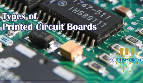
Introduction to PCB Types
Printed circuit boards (PCBs) are the foundation of modern electronics. They provide a platform for mounting and connecting electronic components to create functional circuits and devices. PCBs come in various types, each with its own characteristics, advantages, and applications. The three main types of PCBs are single-sided, double-sided, and multilayer. In this article, we will explore these PCB types in detail, discussing their features, manufacturing processes, and suitable applications.
Single-Sided PCBs
What are Single-Sided PCBs?
Single-sided PCBs, also known as Single-Layer PCBs, have conductive copper traces on only one side of the insulating substrate. The components are mounted on the same side as the copper traces, and the connections between components are made through the conductive paths on the single layer.
Manufacturing Process
The manufacturing process for single-sided PCBs involves the following steps:
- Substrate Preparation: A substrate material, typically FR-4 (a glass-reinforced epoxy laminate), is cut to the desired size and shape.
- Copper Cladding: A thin layer of copper foil is laminated onto one side of the substrate using heat and pressure.
- Drilling: Holes are drilled through the substrate and copper layer to accommodate through-hole components and vias.
- Patterning: The desired circuit pattern is transferred onto the copper layer using a photoresist and exposure to UV light.
- Etching: The exposed copper areas are chemically etched away, leaving only the desired conductive traces.
- Solder Mask Application: A protective solder mask is applied to the PCB surface, leaving only the exposed pads and holes.
- Silkscreen Printing: Text, symbols, and component identifiers are printed onto the solder mask using silkscreen printing.
- Surface Finish: A surface finish, such as HASL (Hot Air Solder Leveling) or ENIG (Electroless Nickel Immersion Gold), is applied to the exposed copper areas to protect them from oxidation and enhance solderability.
Advantages of Single-Sided PCBs
- Cost-effective: Single-sided PCBs are the most economical option due to their simple design and manufacturing process.
- Quick turnaround: The manufacturing process for single-sided PCBs is relatively fast, allowing for shorter lead times.
- Easy to design: Single-sided PCBs have a straightforward design process, making them suitable for beginners and simple projects.
Disadvantages of Single-Sided PCBs
- Limited routing options: With only one conductive layer, single-sided PCBs have limited space for routing traces, which can lead to larger board sizes and reduced design flexibility.
- Limited component density: Single-sided PCBs can accommodate fewer components compared to double-sided and Multilayer PCBs, as all components must be placed on one side of the board.
- Reduced electrical performance: Single-sided PCBs are more susceptible to electromagnetic interference (EMI) and have higher parasitic capacitance and inductance, which can affect signal integrity and high-frequency performance.
Applications
Single-sided PCBs are commonly used in simple, low-cost, and low-density electronic devices, such as:
- Basic electronic hobby projects
- Simple consumer electronics
- Low-power and low-frequency applications
- Educational and prototyping purposes
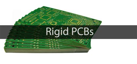
Double-Sided PCBs
What are Double-Sided PCBs?
Double-sided PCBs, also referred to as double-layer PCBs, have conductive copper traces on both sides of the insulating substrate. Components can be mounted on either side of the board, and the two layers are interconnected using vias, which are conductive holes drilled through the substrate.
Manufacturing Process
The manufacturing process for double-sided PCBs is similar to that of single-sided PCBs, with a few additional steps:
- Substrate Preparation: A substrate material, usually FR-4, is cut to the desired size and shape.
- Copper Cladding: Thin layers of copper foil are laminated onto both sides of the substrate using heat and pressure.
- Drilling: Holes are drilled through the substrate and copper layers for through-hole components and vias.
- Patterning: The desired circuit patterns are transferred onto both copper layers using photoresist and UV light exposure.
- Etching: The exposed copper areas are chemically etched away, leaving the desired conductive traces on both sides of the board.
- Via Plating: The drilled holes are plated with conductive material, typically copper, to create electrical connections between the two layers.
- Solder Mask Application: A protective solder mask is applied to both sides of the PCB, leaving only the exposed pads and holes.
- Silkscreen Printing: Text, symbols, and component identifiers are printed onto the solder mask on both sides using silkscreen printing.
- Surface Finish: A surface finish is applied to the exposed copper areas on both sides to protect them from oxidation and enhance solderability.
Advantages of Double-Sided PCBs
- Increased component density: Double-sided PCBs can accommodate more components than single-sided PCBs, as components can be placed on both sides of the board.
- Improved routing options: With two conductive layers, double-sided PCBs offer more space for routing traces, allowing for more complex designs and reduced board sizes.
- Better electrical performance: Double-sided PCBs have improved signal integrity and reduced electromagnetic interference compared to single-sided PCBs, as the two layers can provide better shielding and grounding.
Disadvantages of Double-Sided PCBs
- Higher cost: Double-sided PCBs are more expensive to manufacture than single-sided PCBs due to the additional processing steps and materials required.
- Longer manufacturing time: The manufacturing process for double-sided PCBs is more complex and time-consuming than that of single-sided PCBs, resulting in longer lead times.
- More complex design: Designing double-sided PCBs requires more skill and experience than single-sided PCBs, as designers must consider factors such as via placement, layer alignment, and signal integrity.
Applications
Double-sided PCBs are widely used in various electronic applications that require higher component density, better performance, and more complex designs, such as:
- Consumer electronics (e.g., smartphones, tablets, laptops)
- Industrial control systems
- Automotive electronics
- Medical devices
- Telecommunications equipment

Multilayer PCBs
What are Multilayer PCBs?
Multilayer PCBs have three or more conductive layers, with insulating layers sandwiched between them. The layers are interconnected using vias, which can be through-holes, blind vias (connecting only some of the layers), or buried vias (connecting internal layers only). Multilayer PCBs offer the highest level of design complexity, component density, and performance among the three PCB types.
Manufacturing Process
The manufacturing process for multilayer PCBs is more complex and involves several additional steps compared to single-sided and double-sided PCBs:
- Layer Preparation: The individual layers of the PCB are prepared separately, each with its own substrate, copper cladding, and circuit pattern.
- Lamination: The prepared layers are stacked together with insulating layers (prepreg) between them and laminated under high pressure and temperature to form a solid, multilayer board.
- Drilling: Holes are drilled through the multilayer board for through-hole components and vias.
- Via Plating: The drilled holes are plated with conductive material to create electrical connections between the layers.
- Patterning: The outer layers of the multilayer board are patterned using photoresist and UV light exposure.
- Etching: The exposed copper areas on the outer layers are chemically etched away, leaving the desired conductive traces.
- Solder Mask Application: A protective solder mask is applied to the outer layers, leaving only the exposed pads and holes.
- Silkscreen Printing: Text, symbols, and component identifiers are printed onto the solder mask on the outer layers using silkscreen printing.
- Surface Finish: A surface finish is applied to the exposed copper areas on the outer layers to protect them from oxidation and enhance solderability.
Advantages of Multilayer PCBs
- High component density: Multilayer PCBs can accommodate the highest number of components among the three PCB types, as components can be placed on both outer layers and multiple inner layers.
- Excellent routing options: With multiple conductive layers, multilayer PCBs provide ample space for routing traces, enabling highly complex designs and minimizing board sizes.
- Superior electrical performance: Multilayer PCBs offer the best signal integrity, reduced crosstalk, and minimal electromagnetic interference, as the multiple layers can provide extensive shielding, grounding, and Controlled impedance.
- Compact form factor: Multilayer PCBs allow for the creation of highly compact and dense electronic devices, as the increased number of layers enables more functionality to be packed into a smaller space.
Disadvantages of Multilayer PCBs
- High cost: Multilayer PCBs are the most expensive type of PCB to manufacture due to the complex fabrication process, specialized materials, and advanced equipment required.
- Longer manufacturing time: The manufacturing process for multilayer PCBs is the most time-consuming among the three PCB types, resulting in longer lead times and reduced flexibility for design changes.
- Complex design process: Designing multilayer PCBs requires a high level of skill, experience, and specialized software tools to ensure proper layer stackup, via placement, signal integrity, and thermal management.
Applications
Multilayer PCBs are used in a wide range of advanced electronic applications that demand high performance, reliability, and compact form factors, such as:
- High-end consumer electronics (e.g., gaming consoles, smart watches, virtual reality devices)
- Aerospace and defense systems
- Medical imaging equipment
- High-speed networking devices
- Supercomputers and data centers
Comparison Table
| PCB Type | Layers | Cost | Density | Routing | Performance | Applications |
|---|---|---|---|---|---|---|
| Single-Sided | 1 | Low | Low | Limited | Low | Simple, low-cost devices |
| Double-Sided | 2 | Medium | Medium | Good | Medium | Consumer electronics, industrial |
| Multilayer | 3+ | High | High | Excellent | High | Advanced, high-performance devices |
FAQ
-
Q: What is the main difference between single-sided and double-sided PCBs?
A: Single-sided PCBs have conductive traces on only one side of the substrate, while double-sided PCBs have traces on both sides, allowing for higher component density and better routing options. -
Q: When should I choose a multilayer PCB over a double-sided PCB?
A: Multilayer PCBs are preferred when your design requires very high component density, complex routing, superior electrical performance, or a compact form factor that cannot be achieved with a double-sided PCB. -
Q: Are multilayer PCBs always better than single-sided or double-sided PCBs?
A: Not necessarily. The choice of PCB type depends on the specific requirements of your project, such as budget, timeline, complexity, and performance needs. Single-sided and double-sided PCBs can be more cost-effective and suitable for simpler designs. -
Q: Can I mix different types of components on the same PCB?
A: Yes, you can mix through-hole and surface-mount components on the same PCB, regardless of whether it is single-sided, double-sided, or multilayer. However, the placement and routing of components may be more challenging on single-sided boards. -
Q: How do I choose the right number of layers for my multilayer PCB?
A: The number of layers in a multilayer PCB depends on factors such as the complexity of your design, the number of components, signal integrity requirements, and the desired form factor. Consult with your PCB designer and manufacturer to determine the optimal number of layers for your specific application.
Conclusion
Understanding the differences between single-sided, double-sided, and multilayer PCBs is crucial for selecting the most appropriate type for your electronic project. Each PCB type has its own advantages, disadvantages, and suitable applications. Single-sided PCBs are cost-effective and suitable for simple, low-density designs. Double-sided PCBs offer increased component density and improved routing options, making them a good choice for many consumer and industrial electronics. Multilayer PCBs provide the highest level of design complexity, performance, and component density, but come at a higher cost and longer manufacturing time.
When choosing a PCB type, consider factors such as your project’s budget, timeline, complexity, performance requirements, and intended application. By selecting the right PCB type and working closely with experienced PCB designers and manufacturers, you can ensure the success and reliability of your electronic devices.
No responses yet