Understanding the Role of Inductors in Switching Regulators
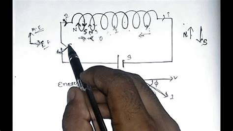
Switching regulators, also known as switch-mode power supplies (SMPS), are widely used in electronic systems to efficiently convert one voltage level to another. These regulators rely on the principle of energy storage and release using inductors and capacitors to achieve the desired voltage conversion. Inductors play a crucial role in the operation of switching regulators by storing energy in their magnetic field during the on-time of the switch and releasing it during the off-time.
Key Functions of Inductors in Switching Regulators
-
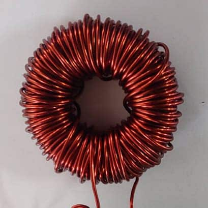
Energy Storage: Inductors store energy in their magnetic field when current flows through them. In a switching regulator, the inductor stores energy during the on-time of the switch.
-
Energy Release: When the switch turns off, the inductor releases the stored energy, providing current to the load and maintaining the output voltage.
-
Current Smoothing: Inductors help to smooth out the current ripple in the switching regulator, reducing output voltage ripple and improving regulation.
-
Frequency Filtering: Inductors, along with capacitors, form a low-pass filter that attenuates high-frequency noise and ripple in the output voltage.
| Component | Function |
|---|---|
| Inductor | Energy storage, current smoothing, filtering |
| Capacitor | Energy storage, voltage smoothing, filtering |
| Switch | Controls the energy transfer and duty cycle |
| Diode | Provides a path for inductor current to flow |
Grounding Considerations for Inductors
Proper grounding is essential for the optimal performance and stability of switching regulators. The placement of ground connections, especially in relation to inductors, can have a significant impact on the regulator’s behavior and electromagnetic compatibility (EMC).
Importance of Grounding in Switching Regulators
-
Minimizing Ground Loops: Proper grounding helps to minimize ground loops, which can cause unwanted noise, oscillations, and instability in the regulator.
-
Reducing Electromagnetic Interference (EMI): Appropriate grounding techniques can help to reduce EMI generated by the switching regulator, ensuring compliance with EMC standards and minimizing interference with other circuits.
-
Improving Thermal Management: Effective grounding can help to dissipate heat generated by the inductor and other components, preventing thermal issues and ensuring reliable operation.
-
Enhancing Stability and Transient Response: Proper grounding contributes to the overall stability and transient response of the switching regulator, ensuring accurate voltage regulation and minimizing output voltage overshoot or undershoot.
Grounding Techniques for Inductors
-
Solid Ground Plane: Using a solid ground plane beneath the inductor can provide a low-impedance return path for high-frequency currents and help to minimize ground loops.
-
Localized Ground Connections: Connecting the inductor’s ground terminal directly to the ground plane or a dedicated ground point near the inductor can reduce the inductance and resistance of the ground connection.
-
Minimize Ground Path Length: Keeping the ground path between the inductor and other components as short as possible helps to reduce parasitic inductance and resistance, improving overall performance.
-
Proper Component Placement: Carefully placing the inductor and other components to minimize ground loops and optimize current flow can contribute to better grounding and overall regulator performance.
| Grounding Technique | Advantages | Disadvantages |
|---|---|---|
| Solid Ground Plane | Low-impedance path, minimizes ground loops | Increased board space, potential EMI issues |
| Localized Ground | Reduces inductance and resistance | May require additional vias or connections |
| Short Ground Path | Minimizes parasitic effects | Layout constraints, component placement |
| Proper Component Placement | Optimizes current flow, reduces ground loops | Requires careful design and layout |
Impact of Ground Placement on Inductor Performance
The placement of ground connections in relation to inductors can significantly affect their performance and the overall behavior of the switching regulator. Let’s explore the impact of ground placement on inductor performance.
Ground Plane Placement
Placing a solid ground plane beneath the inductor has several benefits:
-
Reduced Ground Impedance: A solid ground plane provides a low-impedance return path for high-frequency currents, minimizing ground loops and improving overall regulator performance.
-
Enhanced Shielding: The ground plane acts as a shield, reducing the electromagnetic field coupling between the inductor and other components, thus minimizing EMI.
-
Improved Thermal Dissipation: The ground plane helps to dissipate heat generated by the inductor, preventing thermal issues and ensuring reliable operation.
Localized Ground Connections
Connecting the inductor’s ground terminal directly to the ground plane or a dedicated ground point near the inductor offers the following advantages:
-
Reduced Parasitic Inductance: Localized ground connections minimize the inductance between the inductor and ground, improving high-frequency performance and reducing ringing.
-
Minimized Ground Loops: Direct ground connections help to minimize ground loops, reducing noise and instability in the regulator.
-
Improved Transient Response: Localized grounding contributes to better transient response and stability, ensuring accurate voltage regulation during load changes.
Ground Path Length
Keeping the ground path between the inductor and other components as short as possible is crucial for optimal performance:
-
Reduced Parasitic Effects: Short ground paths minimize parasitic inductance and resistance, reducing their impact on the regulator’s behavior.
-
Improved High-Frequency Performance: Minimizing the ground path length helps to maintain the integrity of high-frequency signals and reduces the potential for signal degradation.
-
Enhanced Stability: Shorter ground paths contribute to improved stability and reduced oscillations in the switching regulator.
| Ground Placement Factor | Impact on Inductor Performance |
|---|---|
| Ground Plane | Reduces ground impedance, enhances shielding, improves thermal dissipation |
| Localized Ground | Minimizes parasitic inductance, reduces ground loops, improves transient response |
| Ground Path Length | Reduces parasitic effects, improves high-frequency performance, enhances stability |

Guidelines for Optimal Inductor Grounding
To ensure the best performance and reliability of inductors in switching regulators, follow these guidelines for optimal grounding:
-
Use a solid ground plane: Whenever possible, place a solid ground plane beneath the inductor to provide a low-impedance return path and enhance shielding.
-
Minimize ground loops: Carefully route the ground connections to minimize ground loops and reduce noise and instability in the regulator.
-
Keep ground paths short: Design the layout to keep the ground paths between the inductor and other components as short as possible, minimizing parasitic effects.
-
Use localized ground connections: Connect the inductor’s ground terminal directly to the ground plane or a dedicated ground point near the inductor to reduce parasitic inductance and improve transient response.
-
Consider component placement: Place the inductor and other components strategically to optimize current flow, minimize ground loops, and reduce EMI.
-
Use appropriate vias: When connecting the inductor to the ground plane, use multiple vias to reduce the inductance and resistance of the ground connection.
-
Avoid ground plane splits: Minimize ground plane splits near the inductor to maintain a continuous low-impedance ground path and prevent ground loops.
-
Simulate and test: Perform simulations and thorough testing to validate the grounding design and ensure optimal inductor performance in the switching regulator.
Frequently Asked Questions (FAQ)
1. What is the purpose of placing ground below inductors in switching regulators?
Placing ground below inductors in switching regulators serves several purposes:
– It provides a low-impedance return path for high-frequency currents, minimizing ground loops and improving overall regulator performance.
– It acts as a shield, reducing electromagnetic field coupling between the inductor and other components, thus minimizing EMI.
– It helps to dissipate heat generated by the inductor, preventing thermal issues and ensuring reliable operation.
2. How does ground placement affect inductor performance?
Ground placement significantly affects inductor performance in switching regulators. Proper ground placement, such as using a solid ground plane beneath the inductor and localized ground connections, can reduce ground impedance, minimize parasitic effects, improve high-frequency performance, and enhance stability. On the other hand, poor ground placement can lead to increased ground loops, noise, instability, and degraded transient response.
3. What are the advantages of using a solid ground plane beneath inductors?
Using a solid ground plane beneath inductors offers several advantages:
– It provides a low-impedance return path for high-frequency currents, reducing ground loops and improving overall regulator performance.
– It enhances shielding, reducing electromagnetic field coupling between the inductor and other components, thus minimizing EMI.
– It improves thermal dissipation, helping to dissipate heat generated by the inductor and ensuring reliable operation.
4. Why is it important to keep the ground path between the inductor and other components short?
Keeping the ground path between the inductor and other components short is crucial for optimal performance because:
– It minimizes parasitic inductance and resistance, reducing their impact on the regulator’s behavior.
– It helps to maintain the integrity of high-frequency signals and reduces the potential for signal degradation.
– It contributes to improved stability and reduced oscillations in the switching regulator.
5. What are some guidelines for optimal inductor grounding in switching regulators?
Some guidelines for optimal inductor grounding in switching regulators include:
– Using a solid ground plane beneath the inductor whenever possible.
– Minimizing ground loops through careful routing of ground connections.
– Keeping ground paths short to minimize parasitic effects.
– Using localized ground connections to reduce parasitic inductance and improve transient response.
– Considering component placement to optimize current flow, minimize ground loops, and reduce EMI.
– Using appropriate vias to reduce the inductance and resistance of the ground connection.
– Avoiding ground plane splits near the inductor to maintain a continuous low-impedance ground path.
– Performing simulations and thorough testing to validate the grounding design and ensure optimal inductor performance.
Conclusion
Proper grounding is essential for the optimal performance and reliability of inductors in switching regulators. The placement of ground connections, especially in relation to inductors, can significantly impact the regulator’s behavior, stability, and electromagnetic compatibility.
By understanding the role of inductors in switching regulators and the importance of grounding considerations, designers can make informed decisions about ground placement. Using techniques such as solid ground planes, localized ground connections, and minimizing ground path lengths, designers can optimize inductor performance and ensure the overall stability and reliability of the switching regulator.
Following the guidelines for optimal inductor grounding, along with careful simulation and testing, can help to minimize ground loops, reduce EMI, improve thermal management, and enhance the transient response of the regulator.
As switching regulators continue to be widely used in various electronic systems, proper inductor grounding remains a critical aspect of their design. By paying attention to ground placement and implementing best practices, designers can unlock the full potential of inductors in switching regulators and achieve efficient, stable, and reliable voltage conversion.
No responses yet