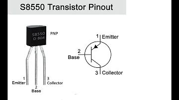
What is an S8550 Transistor?
The S8550 is a PNP bipolar junction transistor (BJT) that is commonly used as a general-purpose amplifier and switch in electronic circuits. It is part of the S8550/S8050 complementary pair, where the S8550 is the PNP transistor, and the S8050 is its NPN counterpart.
Key Characteristics of the S8550 Transistor
| Parameter | Value |
|---|---|
| Polarity | PNP |
| Maximum Collector-Emitter Voltage (VCE) | -25V |
| Maximum Collector Current (IC) | -1.5A |
| Maximum Power Dissipation (Pd) | 625mW |
| Current Gain (hFE) | 110-220 |
| Transition Frequency (fT) | 150MHz |
The S8550 transistor has three terminals: emitter (E), base (B), and collector (C). The emitter is the source of charge carriers (holes), the base controls the flow of charge carriers, and the collector is where the charge carriers are collected.
How Does an S8550 Transistor Work?
The S8550 transistor works by controlling the flow of current between the emitter and collector terminals using a small current applied to the base terminal. When a small current flows into the base, it allows a much larger current to flow from the emitter to the collector.
Biasing an S8550 Transistor
To properly bias an S8550 transistor, you need to ensure that the base-emitter junction is forward-biased and the base-collector junction is reverse-biased. This is typically achieved by applying a negative voltage to the base with respect to the emitter and a more negative voltage to the collector.
Here’s an example of a basic biasing circuit for an S8550 transistor:
         +VCC
          |
          |
          /
         < R1
          \
          |
          +-----+
          |     |
          |    C|
          +-----|
               |
              B|
               |
          +-----|
          |     |
          |    E|
          +-----+
          |
          |
         ///
         GND
In this circuit, R1 is the base resistor that limits the base current, and VCC is the supply voltage. The emitter is connected to ground (GND), and the collector is connected to the load (not shown).
S8550 Transistor as an Amplifier
One of the primary applications of the S8550 transistor is as an amplifier. In an amplifier circuit, the transistor is biased to operate in its active region, where small changes in the base current result in large changes in the collector current.
Here’s an example of a basic common-emitter amplifier circuit using an S8550 transistor:
         +VCC
          |
          |
          /
         < R1
          \
          |
          +-----+
          |     |
         C|    C|
          |     |
          +--+--+
             |
            B|
             |
      +------+------+
      |             |
     ///           ///
    Input         Output
In this circuit, the input signal is applied to the base through a coupling capacitor, and the amplified output signal is taken from the collector. R1 sets the DC bias point, and the coupling capacitor blocks any DC component from the input signal.
Applications of S8550 Transistors
S8550 transistors find use in a wide range of electronic applications, including:
- Audio amplifiers
- Switching circuits
- Voltage regulators
- Logic gates
- Motor drivers
Example: S8550 Transistor as a Switch
One common application of the S8550 transistor is as a switch. In this configuration, the transistor is used to control the flow of current through a load, such as a relay or an LED.
Here’s an example of an S8550 transistor used as a switch to control an LED:
         +VCC
          |
          |
          /
         < R1
          \
          |
          +-----+
          |     |
          |    C|
          +-----|---->|----+
               |           |
              B|          LED
               |           |
          +-----|           |
          |     |           |
          |    E|           |
          +-----+           |
          |                 |
          |                 |
         ///               ///
         GND               GND
In this circuit, when a positive voltage is applied to the base through R1, the transistor turns on, allowing current to flow through the LED, causing it to light up. When the base voltage is removed, the transistor turns off, and the LED turns off.

FAQ
-
Q: What is the difference between an S8550 and an S8050 transistor?
A: The S8550 is a PNP transistor, while the S8050 is an NPN transistor. They have complementary characteristics and are often used together in push-pull configurations. -
Q: Can I replace an S8550 transistor with another PNP transistor?
A: In most cases, yes, as long as the replacement transistor has similar or better specifications, such as voltage and current ratings, power dissipation, and gain. -
Q: What happens if I connect the S8550 transistor incorrectly?
A: Connecting the transistor incorrectly can lead to malfunction or permanent damage. Always ensure that the emitter, base, and collector terminals are connected correctly according to the circuit diagram. -
Q: How do I test an S8550 transistor?
A: You can test an S8550 transistor using a multimeter in the diode test mode. Check the resistance between the base-emitter and base-collector junctions; a functioning transistor should show a low resistance in one direction and a high resistance in the other. -
Q: What is the maximum power dissipation of an S8550 transistor?
A: The maximum power dissipation of an S8550 transistor is 625mW. Ensure that your circuit design does not exceed this limit to prevent damage to the transistor.
Conclusion
The S8550 transistor is a versatile PNP bipolar junction transistor that finds use in numerous electronic applications, such as amplifiers, switches, and voltage regulators. By understanding its characteristics and proper biasing techniques, you can effectively incorporate the S8550 transistor into your projects. Always refer to the transistor’s datasheet for detailed specifications and design considerations.

No responses yet