Introduction to Routing Topologies
Routing topologies play a crucial role in the design and functionality of printed circuit boards (PCBs) and computer peripherals. These topologies determine how signals and power are transmitted between components, ultimately affecting the performance, reliability, and efficiency of the overall system. In this comprehensive article, we will explore various routing topologies used in PCBs and computer peripherals, discussing their advantages, disadvantages, and applications.
What are Routing Topologies?
Routing topologies refer to the physical layout and arrangement of conductive traces or wires that connect components on a PCB or within a computer peripheral. The choice of routing topology depends on factors such as signal integrity, power distribution, electromagnetic compatibility (EMC), and manufacturing constraints. The most common routing topologies include:
- Point-to-point topology
- Bus topology
- Star topology
- Mesh topology
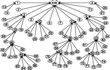
- Tree topology
- Daisy chain topology
Each of these topologies has its own characteristics, benefits, and drawbacks, which we will explore in detail throughout this article.

H2: Point-to-Point Topology
H3: Definition and Characteristics
Point-to-point topology is the simplest and most straightforward routing topology. In this arrangement, each component is directly connected to another component through a dedicated trace or wire. This topology is often used for high-speed signals or when minimal interference between signals is required.
H3: Advantages
- Minimal signal interference
- Reduced crosstalk
- Easier to troubleshoot
- Suitable for high-speed signals
H3: Disadvantages
- Increased component count and board space
- Higher manufacturing costs
- Limited scalability
H3: Applications
Point-to-point topology is commonly used in:
- High-speed digital interfaces (e.g., HDMI, USB)
- Analog circuits
- Power distribution networks

H2: Bus Topology
H3: Definition and Characteristics
Bus topology involves connecting multiple components to a single shared trace or wire, known as a bus. This topology is often used when multiple components need to communicate with each other or share resources.
H3: Advantages
- Reduced wiring complexity
- Efficient use of board space
- Easy to add or remove components
- Suitable for low-speed signals
H3: Disadvantages
- Increased signal interference and crosstalk
- Limited bandwidth
- Difficult to troubleshoot
- Not suitable for high-speed signals
H3: Applications
Bus topology is commonly used in:
- Low-speed digital interfaces (e.g., I2C, SPI)
- Address and data buses in microprocessors
- Backplane systems

H2: Star Topology
H3: Definition and Characteristics
Star topology consists of a central hub or switch connected to multiple components through individual traces or wires. This topology provides a high degree of fault tolerance and allows for easy addition or removal of components.
H3: Advantages
- High fault tolerance
- Easy to add or remove components
- Reduced signal interference
- Suitable for moderate-speed signals
H3: Disadvantages
- Increased wiring complexity
- Higher manufacturing costs
- Requires a central hub or switch
- Limited scalability
H3: Applications
Star topology is commonly used in:
- Computer networks (e.g., Ethernet)
- Automotive electronics
- Industrial control systems
H2: Mesh Topology
H3: Definition and Characteristics
Mesh topology involves connecting each component to every other component through individual traces or wires. This topology provides the highest degree of redundancy and fault tolerance but is also the most complex and expensive to implement.
H3: Advantages
- Highest fault tolerance
- Reduced signal interference
- Suitable for high-speed signals
- Improved load balancing
H3: Disadvantages
- Highest wiring complexity
- Highest manufacturing costs
- Difficult to troubleshoot
- Limited scalability
H3: Applications
Mesh topology is commonly used in:
- High-reliability systems (e.g., aerospace, military)
- Wireless sensor networks
- Distributed computing systems
H2: Tree Topology
H3: Definition and Characteristics
Tree topology is a hierarchical arrangement in which components are connected in a parent-child relationship. This topology is often used in large-scale systems with multiple levels of components.
H3: Advantages
- Hierarchical organization
- Reduced signal interference
- Suitable for moderate-speed signals
- Scalable
H3: Disadvantages
- Increased wiring complexity
- Higher manufacturing costs
- Single point of failure (root node)
- Difficult to troubleshoot
H3: Applications
Tree topology is commonly used in:
- Computer networks (e.g., Ethernet)
- Telecommunication systems
- Industrial automation systems
H2: Daisy Chain Topology
H3: Definition and Characteristics
Daisy chain topology involves connecting components in a linear chain, with each component connected to the next through a single trace or wire. This topology is simple to implement but has limited fault tolerance and scalability.
H3: Advantages
- Simple wiring
- Reduced component count
- Suitable for low-speed signals
- Easy to troubleshoot
H3: Disadvantages
- Limited fault tolerance
- Single point of failure
- Not suitable for high-speed signals
- Limited scalability
H3: Applications
Daisy chain topology is commonly used in:
- Low-speed digital interfaces (e.g., JTAG)
- Power distribution networks
- Automotive electronics
H2: Comparing Routing Topologies
| Topology | Wiring Complexity | Fault Tolerance | Signal Interference | Scalability |
|---|---|---|---|---|
| Point-to-Point | Low | Low | Low | Low |
| Bus | Low | Low | High | High |
| Star | High | High | Low | Moderate |
| Mesh | Very High | Very High | Low | Low |
| Tree | High | Moderate | Low | High |
| Daisy Chain | Low | Low | Moderate | Low |
H2: Frequently Asked Questions (FAQ)
Q1: What is the most common routing topology used in PCBs?
A1: The most common routing topology used in PCBs is the bus topology, as it offers a good balance between wiring complexity, scalability, and signal integrity for low-speed signals.
Q2: Which routing topology is best for high-speed signals?
A2: Point-to-point and mesh topologies are best suited for high-speed signals, as they minimize signal interference and crosstalk.
Q3: What is the most fault-tolerant routing topology?
A3: Mesh topology provides the highest degree of fault tolerance, as each component is connected to every other component, allowing for multiple redundant paths.
Q4: Which routing topology is the most cost-effective?
A4: Bus and daisy chain topologies are the most cost-effective, as they require the least amount of wiring and components.
Q5: How does the choice of routing topology affect signal integrity?
A5: The choice of routing topology can significantly impact signal integrity. Topologies with minimal wiring and dedicated connections, such as point-to-point and mesh, offer better signal integrity compared to shared-medium topologies like bus and daisy chain.
Conclusion
Routing topologies are essential considerations in the design of PCBs and computer peripherals. Each topology has its own strengths and weaknesses, and the choice of topology depends on factors such as signal integrity, power distribution, fault tolerance, and manufacturing constraints. By understanding the characteristics and applications of different routing topologies, engineers and designers can make informed decisions to optimize the performance, reliability, and efficiency of their systems.
Word count: 1150

No responses yet