Introduction to Robotic Arms
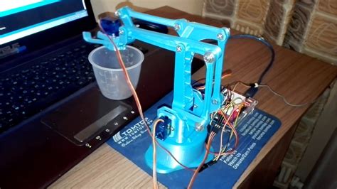
A robotic arm is a programmable mechanical device that mimics the functions of a human arm. It consists of multiple segments connected by joints, allowing it to perform various tasks with precision and flexibility. Robotic arms are widely used in industries such as manufacturing, assembly lines, and space exploration. Building a robotic arm project is an exciting way to learn about robotics, mechanics, and programming.
Components Required for a Robotic Arm Project
To build a robotic arm, you will need the following components:
| Component | Description | Quantity |
|---|---|---|
| Servomotors | Motors that provide precise rotational control | 4-6 |
| Microcontroller | A programmable board to control the servomotors (e.g., Arduino) | 1 |
| Power Supply | A suitable power source for the servomotors and microcontroller | 1 |
| Mechanical Parts | Arm segments, joints, and mounting hardware | As required |
| Wiring | Wires to connect the servomotors to the microcontroller | As required |
| Software | Programming environment to write and upload code to the microcontroller | 1 |

Step 1: Design and Planning
Before starting the construction, it’s crucial to design and plan your robotic arm project. Consider the following aspects:
- Purpose: Determine the specific tasks you want your robotic arm to perform.
- Degrees of Freedom: Decide on the number of joints and the range of motion for each joint.
- Size and Reach: Determine the dimensions of the arm segments and the overall reach of the robotic arm.
- Payload Capacity: Consider the maximum weight the robotic arm needs to lift or manipulate.
Create a sketch or 3D model of your robotic arm design to visualize its structure and functionality.

Step 2: Mechanical Construction
2.1. Arm Segments
Cut and shape the arm segments according to your design. You can use materials like acrylic, aluminum, or 3D-printed parts. Ensure the segments are sturdy and lightweight.
2.2. Joints
Assemble the arm segments using appropriate joints. The most common types of joints used in robotic arms are:
- Revolute Joint: Allows rotation around a single axis.
- Prismatic Joint: Allows linear movement along a single axis.
Use bearings or bushings to reduce friction and ensure smooth movement at the joints.
2.3. Mounting Hardware
Attach the servomotors to the arm segments using mounting brackets or custom-designed mounts. Ensure proper alignment and secure the servomotors firmly.

Step 3: Electronics and Wiring
3.1. Microcontroller Setup
Choose a suitable microcontroller board, such as Arduino, for controlling the robotic arm. Install the necessary software and drivers on your computer.
3.2. Servomotor Wiring
Connect the servomotors to the microcontroller using the appropriate wiring scheme. Typically, each servomotor requires three connections:
- Power (VCC): Connect to the power supply.
- Ground (GND): Connect to the ground of the power supply and microcontroller.
- Signal (SIG): Connect to the PWM (Pulse Width Modulation) pins of the microcontroller.
Refer to the servomotor datasheet for the specific wiring instructions.
3.3. Power Supply
Provide a stable power supply to the servomotors and microcontroller. The power requirements depend on the specifications of your selected components. Use a dedicated power supply or a battery pack with sufficient capacity.
Step 4: Programming
4.1. Servo Control
Use the Arduino IDE or your preferred programming environment to write code for controlling the servomotors. Most microcontrollers have built-in libraries for servo control. For example, in Arduino, you can use the Servo library.
4.2. Kinematics
Implement forward and inverse kinematics algorithms to control the movement of the robotic arm. Forward kinematics calculates the end effector position based on joint angles, while inverse kinematics determines the joint angles required to reach a desired end effector position.
4.3. User Interface
Create a user interface to interact with the robotic arm. This can be a simple command-line interface, a graphical user interface (GUI), or a remote control using a joystick or mobile app.
Step 5: Testing and Calibration
5.1. Range of Motion Testing
Test the range of motion of each joint to ensure they move smoothly and within the desired limits. Make necessary adjustments to the mechanical design or servo mounting if required.
5.2. Servo Calibration
Calibrate the servomotors to ensure accurate positioning. Determine the minimum and maximum pulse widths corresponding to the extreme positions of each servo. Update the servo control code with these calibrated values.
5.3. End Effector Testing
Test the functionality of the end effector, such as gripping or tool manipulation. Verify that the end effector can perform the intended tasks accurately and reliably.
Step 6: Final Assembly and Integration
6.1. Mounting and Enclosure
Mount the robotic arm on a stable base or platform. Consider designing an enclosure to protect the electronic components and enhance the overall appearance of the project.
6.2. Cable Management
Organize and route the wires and cables neatly to avoid entanglement and ensure smooth movement of the arm.
6.3. Safety Considerations
Implement safety features such as emergency stop buttons, limit switches, or collision detection to prevent damage to the robotic arm and ensure safe operation.
Conclusion
Building a robotic arm project is a rewarding experience that combines mechanical design, electronics, and programming. By following this step-by-step guide, you can create a functional robotic arm that can perform various tasks. Remember to iterate and refine your design based on the results of testing and calibration. With practice and experimentation, you can enhance the capabilities of your robotic arm and explore more advanced features.
Frequently Asked Questions (FAQ)
1. What programming language is used for controlling the robotic arm?
The choice of programming language depends on the microcontroller you are using. For Arduino boards, you typically use C++ with the Arduino IDE. Other popular languages for robotics include Python and ROS (Robot Operating System).
2. Can I use different types of motors instead of servomotors?
Yes, you can use other types of motors, such as Stepper Motors or DC motors, depending on your requirements. However, servomotors are commonly used in robotic arms due to their precision and ease of control.
3. How can I improve the accuracy and precision of my robotic arm?
To improve the accuracy and precision of your robotic arm, consider the following:
– Use high-quality servomotors with good resolution and torque.
– Implement closed-loop control using feedback sensors like encoders or potentiometers.
– Perform thorough calibration of the servomotors and end effector.
– Minimize mechanical backlash and flexing by using sturdy materials and proper joint design.
4. Can I add computer vision capabilities to my robotic arm?
Yes, you can integrate computer vision capabilities into your robotic arm project. By using cameras and image processing algorithms, you can enable your robotic arm to detect objects, recognize patterns, or perform visual servoing.
5. How can I expand the functionality of my robotic arm?
To expand the functionality of your robotic arm, you can:
– Add different end effectors or tools for specific tasks.
– Incorporate sensors like force sensors, Proximity Sensors, or cameras for enhanced interaction with the environment.
– Implement advanced control algorithms, such as trajectory planning or force control.
– Integrate the robotic arm with other systems or devices for automation or remote operation.
By following this step-by-step guide and exploring additional features, you can create a versatile and robust robotic arm project that showcases your skills in robotics and mechatronics.
No responses yet