Introduction to Rigid-Flex PCBs
In today’s rapidly advancing technological landscape, Printed Circuit Boards (PCBs) have become an indispensable component of electronic devices. Among the various types of PCBs, Rigid-Flex PCBs have gained significant popularity due to their unique combination of rigidity and flexibility. This ultimate guide will delve into the world of Rigid-Flex PCBs, exploring their benefits, applications, design considerations, and manufacturing processes.
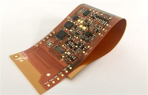
What is a Rigid-Flex PCB?
A Rigid-Flex PCB is a hybrid circuit board that combines the stability of rigid PCBs with the flexibility of flexible circuits. It consists of multiple layers of flexible and rigid substrates laminated together to form a single, unified structure. The flexible portions allow for bending and folding, while the rigid areas provide structural support and accommodate components.
Key Features of Rigid-Flex PCBs
- Combination of rigid and flexible substrates
- Ability to bend and fold in specific areas
- Increased reliability and durability
- Reduced overall size and weight
- Enhanced signal integrity

Benefits of Using Rigid-Flex PCBs
Space Savings and Miniaturization
One of the primary advantages of Rigid-Flex PCBs is their ability to save space and enable miniaturization. By incorporating flexible circuits, designers can create more compact and efficient layouts. The flexible portions can be folded or bent to fit into tight spaces, reducing the overall footprint of the device.
Improved Reliability and Durability
Rigid-Flex PCBs offer enhanced reliability and durability compared to traditional PCBs. The flexible segments absorb stress and vibrations, reducing the risk of mechanical failures. Additionally, the elimination of connectors and cables between rigid boards minimizes potential points of failure, resulting in a more robust and reliable system.
Enhanced Signal Integrity
The integrated nature of Rigid-Flex PCBs allows for shorter signal paths and reduced electromagnetic interference (EMI). By eliminating the need for connectors and cables, signal integrity is maintained, leading to improved performance and reduced noise. This is particularly important in high-speed and high-frequency applications.
Cost Reduction and Simplified Assembly
Although the initial cost of Rigid-Flex PCBs may be higher than traditional PCBs, they offer long-term cost savings through simplified assembly and reduced component count. The elimination of connectors and cables streamlines the assembly process, reducing labor costs and minimizing the risk of human error.

Applications of Rigid-Flex PCBs
Rigid-Flex PCBs find applications across various industries due to their unique capabilities. Some common applications include:
- Aerospace and Defense
- Avionics systems
- Satellite communication devices
-
Military equipment
-
Medical Devices
- Wearable medical monitors
- Implantable devices
-
Diagnostic equipment
-
Consumer Electronics
- Smartphones and tablets
- Wearable technology
-
Gaming devices
-
Automotive Industry
- In-vehicle infotainment systems
- Advanced driver assistance systems (ADAS)
-
Electric vehicle battery management systems
-
Industrial Automation
- Robotics and motion control
- Industrial sensors and monitoring devices
- Industrial communication systems

Rigid-Flex PCB Design Considerations
Designing Rigid-Flex PCBs requires careful consideration of various factors to ensure optimal performance and manufacturability. Some key design considerations include:
Layer Stack-up and Material Selection
The layer stack-up of a Rigid-Flex PCB plays a crucial role in its performance and reliability. Designers must carefully select the appropriate materials for both the rigid and flexible portions, considering factors such as dielectric constant, thermal properties, and flexibility. Proper layer stack-up design ensures signal integrity and prevents issues like delamination and warpage.
Bend Radius and Flexibility
When designing the flexible portions of a Rigid-Flex PCB, it is essential to consider the bend radius and flexibility requirements. The bend radius refers to the minimum radius at which the flexible circuit can be bent without causing damage or affecting its performance. Designers must ensure that the bend radius is within the acceptable range for the chosen materials and layer stack-up.
Component Placement and Routing
Component placement and routing on Rigid-Flex PCBs require careful planning to optimize space utilization and ensure proper functionality. Designers must consider the placement of components on both the rigid and flexible portions, taking into account factors such as mechanical stress, thermal management, and signal integrity. Routing of traces should be done in a way that minimizes the risk of signal degradation and crosstalk.
Mechanical Stress Analysis
Rigid-Flex PCBs are subject to various mechanical stresses during assembly and operation. Designers must perform mechanical stress analysis to ensure that the PCB can withstand the expected loads and vibrations. This analysis helps identify potential weak points and allows for necessary reinforcements or design modifications to improve the overall reliability of the PCB.
Design for Manufacturability (DFM)
To ensure successful manufacturing of Rigid-Flex PCBs, designers must adhere to Design for Manufacturability (DFM) guidelines. DFM considerations include proper clearances, minimum trace widths, and spacing requirements. Collaborating with the manufacturing team during the design phase can help identify and resolve any potential manufacturing challenges early in the process.
Manufacturing Process of Rigid-Flex PCBs
The manufacturing process of Rigid-Flex PCBs involves several steps to achieve the desired combination of rigidity and flexibility. The key stages of the manufacturing process include:
- Material Selection and Preparation
- Choosing appropriate materials for rigid and flexible portions
-
Cutting and preparing the substrates
-
Lamination
- Bonding the flexible and rigid layers together
-
Applying heat and pressure to form a unified structure
-
Drilling and Plating
- Drilling through-holes and vias
-
Plating the holes to establish electrical connections
-
Patterning and Etching
- Applying photoresist and exposing the desired circuit pattern
-
Etching away unwanted copper to form the circuit traces
-
Solder Mask Application
- Applying solder mask to protect the circuit traces
-
Exposing and developing the solder mask
-
Surface Finishing
- Applying surface finishes such as HASL, ENIG, or OSP
-
Protecting the exposed copper and enhancing solderability
-
Outline Routing and Singulation
- Routing the outline of the Rigid-Flex PCB
-
Singulating individual boards from the panel
-
Testing and Inspection
- Performing electrical and visual inspections
- Ensuring the functionality and quality of the manufactured PCBs
Challenges and Considerations in Rigid-Flex PCB Manufacturing
While Rigid-Flex PCBs offer numerous benefits, their manufacturing process presents unique challenges and considerations. Some of these challenges include:
- Material Compatibility
- Ensuring compatibility between the rigid and flexible materials
-
Selecting materials with similar thermal expansion coefficients
-
Lamination Process
- Achieving proper bonding between the layers
-
Preventing delamination and warpage during the lamination process
-
Controlled Impedance
- Maintaining consistent impedance throughout the PCB
-
Designing and manufacturing to meet specific impedance requirements
-
Strain Relief
- Incorporating strain relief features to prevent damage during flexing
-
Designing proper transition zones between rigid and flexible portions
-
Cost Considerations
- Balancing the benefits of Rigid-Flex PCBs with the associated manufacturing costs
- Optimizing the design to minimize material usage and processing steps
Future Trends and Advancements in Rigid-Flex PCBs
As technology continues to evolve, Rigid-Flex PCBs are expected to play an increasingly important role in various industries. Some future trends and advancements in Rigid-Flex PCBs include:
- Increased Adoption in Wearable Devices
- Leveraging the flexibility and durability of Rigid-Flex PCBs for wearable technology
-
Enabling the development of more comfortable and unobtrusive wearable devices
-
Advancements in Materials
- Development of new materials with improved electrical and mechanical properties
-
Exploration of bio-compatible materials for medical applications
-
Integration of Embedded Components
- Incorporating passive and active components within the layers of Rigid-Flex PCBs
-
Further reducing the size and increasing the functionality of electronic devices
-
Advancements in Manufacturing Processes
- Improving the precision and efficiency of Rigid-Flex PCB manufacturing
-
Implementing automation and advanced process control techniques
-
Increased Adoption in 5G and IoT Applications
- Utilizing Rigid-Flex PCBs in the development of 5G infrastructure and devices
- Enabling the creation of compact and reliable IoT sensors and modules
Frequently Asked Questions (FAQ)
- What is the difference between a Rigid-Flex PCB and a traditional PCB?
-
A Rigid-Flex PCB combines both rigid and flexible substrates, allowing for bending and folding in specific areas. Traditional PCBs are entirely rigid and do not have flexible portions.
-
What are the benefits of using Rigid-Flex PCBs?
-
Rigid-Flex PCBs offer benefits such as space savings, improved reliability, enhanced signal integrity, and simplified assembly. They enable the creation of more compact and efficient electronic devices.
-
In which industries are Rigid-Flex PCBs commonly used?
-
Rigid-Flex PCBs find applications in various industries, including aerospace, medical devices, consumer electronics, automotive, and industrial automation.
-
What are some key design considerations for Rigid-Flex PCBs?
-
Key design considerations for Rigid-Flex PCBs include layer stack-up, material selection, bend radius, component placement, routing, mechanical stress analysis, and Design for Manufacturability (DFM).
-
What are the challenges in manufacturing Rigid-Flex PCBs?
- Manufacturing Rigid-Flex PCBs presents challenges such as material compatibility, achieving proper lamination, maintaining controlled impedance, incorporating strain relief, and cost considerations.
Conclusion
Rigid-Flex PCBs have revolutionized the electronic industry by offering a unique combination of rigidity and flexibility. Their ability to save space, improve reliability, enhance signal integrity, and simplify assembly has made them a preferred choice for various applications. As technology continues to advance, Rigid-Flex PCBs are expected to play a crucial role in enabling the development of more compact, reliable, and innovative electronic devices.
When designing and manufacturing Rigid-Flex PCBs, it is essential to consider factors such as material selection, bend radius, component placement, routing, and mechanical stress analysis. Adhering to Design for Manufacturability (DFM) guidelines and collaborating with experienced manufacturing partners can help overcome the challenges associated with Rigid-Flex PCB production.
As we look towards the future, the adoption of Rigid-Flex PCBs is expected to grow in industries such as wearable devices, 5G, and IoT. Advancements in materials, manufacturing processes, and the integration of embedded components will further enhance the capabilities and applications of Rigid-Flex PCBs.
By understanding the benefits, design considerations, and manufacturing processes of Rigid-Flex PCBs, engineers and designers can leverage this technology to create innovative and efficient electronic solutions. Embracing the power of Rigid-Flex PCBs will enable businesses to stay ahead in the rapidly evolving technological landscape.
No responses yet