
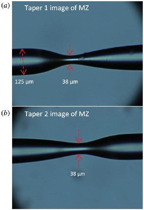
Introduction to RF Trace Taper
In high-frequency printed circuit board (PCB) design, the concept of trace taper plays a crucial role in ensuring optimal signal integrity and minimizing reflections. RF trace taper refers to the gradual change in the width of a transmission line along its length, typically used when transitioning between different impedance sections or connecting to components with varying geometries.
Why is Trace Taper Important?
Trace taper is essential in RF PCB design for several reasons:
-
Impedance Matching: By gradually changing the width of a trace, designers can match the impedance between different sections of a transmission line or components, minimizing reflections and ensuring efficient power transfer.
-
Bandwidth Enhancement: Proper trace tapering helps maintain a consistent characteristic impedance over a wide frequency range, thus improving the bandwidth of the system.
-
Signal Integrity: Tapered traces reduce discontinuities and abrupt changes in the signal path, minimizing reflections, ringing, and other signal integrity issues.
-
Reduced EMI: Gradual transitions between trace widths help minimize electromagnetic interference (EMI) by reducing the abrupt changes in the current flow.
Types of Trace Tapers
There are several types of trace tapers used in RF PCB design, each with its own characteristics and applications.
Linear Taper
A linear taper is the simplest form of trace taper, where the width of the trace changes at a constant rate along its length. The taper length is determined by the desired impedance change and the PCB material properties.
Advantages of Linear Taper
- Easy to design and implement
- Suitable for short taper lengths
- Provides a good compromise between performance and simplicity
Disadvantages of Linear Taper
- May not provide the best performance for long taper lengths or large impedance changes
- Requires more space compared to other taper types
Exponential Taper
An exponential taper is a more advanced form of trace taper, where the width of the trace changes exponentially along its length. This type of taper provides a smoother transition between impedance sections and offers better performance compared to linear tapers.
Advantages of Exponential Taper
- Provides a smoother impedance transition
- Offers better performance for long taper lengths and large impedance changes
- Reduces reflections and improves signal integrity
Disadvantages of Exponential Taper
- More complex to design and implement compared to linear tapers
- Requires precise control over the PCB manufacturing process
Klopfenstein Taper
The Klopfenstein taper, also known as the Dolph-Chebyshev taper, is an optimized taper profile that minimizes reflections and provides the best possible performance for a given taper length. This type of taper is based on the Chebyshev polynomial and offers a near-ideal impedance transition.
Advantages of Klopfenstein Taper
- Provides the best possible performance for a given taper length
- Minimizes reflections and improves signal integrity
- Suitable for applications requiring the highest level of performance
Disadvantages of Klopfenstein Taper
- Most complex to design and implement
- Requires advanced mathematical modeling and simulation tools
- May not be necessary for all applications
Designing RF Trace Tapers
When designing RF trace tapers, several factors must be considered to ensure optimal performance and manufacturability.
Determining Taper Length
The taper length is a critical parameter in RF trace taper design, as it directly affects the performance and space requirements of the taper. The optimal taper length depends on several factors, including:
- The desired impedance change
- The frequency range of operation
- The PCB material properties
- The available space on the PCB
To determine the appropriate taper length, designers can use various techniques, such as:
- Analytical calculations based on transmission line theory
- Electromagnetic simulation tools (e.g., HFSS, CST, ADS)
- Empirical formulas and design guidelines
Choosing the Right Taper Type
Selecting the appropriate taper type is essential for achieving the desired performance and meeting the design constraints. Factors to consider when choosing a taper type include:
- The required level of performance
- The complexity of the design and implementation
- The available space on the PCB
- The manufacturing capabilities and constraints
In general, linear tapers are suitable for simple designs and short taper lengths, while exponential and Klopfenstein tapers offer better performance for more demanding applications.
Impedance Matching Considerations
Proper impedance matching is crucial for minimizing reflections and ensuring efficient power transfer in RF systems. When designing trace tapers, designers must consider the characteristic impedance of the transmission lines, the impedance of the connected components, and the desired matching level.
Common impedance matching techniques used in conjunction with trace tapers include:
- Quarter-wave transformers
- Tapered lines
- Lumped element matching networks
The choice of the matching technique depends on the specific application, frequency range, and design constraints.
Simulation and Optimization
To ensure the optimal performance of RF trace tapers, designers rely on electromagnetic simulation tools and optimization techniques. These tools allow designers to:
- Analyze the impedance profile along the taper
- Evaluate the reflection and transmission characteristics
- Optimize the taper geometry for best performance
- Verify the design before fabrication
Popular simulation tools for RF trace taper design include:
- Ansys HFSS
- CST Studio Suite
- Keysight ADS
- Sonnet Software
By using these tools, designers can fine-tune their taper designs and ensure that they meet the desired performance criteria.

Manufacturing Considerations
When implementing RF trace tapers on a PCB, several manufacturing considerations must be taken into account to ensure the design’s integrity and reliability.
PCB Material Selection
The choice of PCB material plays a crucial role in the performance of RF trace tapers. Key material properties to consider include:
- Dielectric constant (Dk)
- Dissipation factor (Df)
- Thermal stability
- Copper surface roughness
Common PCB materials used for RF applications include:
- FR-4
- Rogers RO4000 series
- Isola I-Tera MT40
- Taconic RF-35
The selection of the appropriate material depends on the frequency range, the required performance, and the cost constraints of the project.
Fabrication Tolerances
Tight fabrication tolerances are essential for maintaining the designed impedance profile and ensuring the proper functioning of RF trace tapers. Key aspects to control during the manufacturing process include:
- Trace width and spacing
- Copper thickness
- Dielectric thickness
- Via size and placement
Designers must work closely with PCB manufacturers to ensure that the fabrication process meets the required tolerances and that the resulting PCB matches the designed specifications.
Testing and Validation
After fabrication, it is essential to test and validate the performance of RF trace tapers to ensure that they meet the design requirements. Common testing techniques include:
- Time-domain reflectometry (TDR)
- Vector network analyzer (VNA) measurements
- Eye diagram analysis
- Bit error rate (BER) testing
By thoroughly testing the manufactured PCBs, designers can identify any issues related to the trace tapers and take corrective actions if necessary.
Applications of RF Trace Tapers
RF trace tapers find applications in a wide range of high-frequency systems, including:
- Wireless communication devices (e.g., smartphones, tablets, laptops)
- Radar systems
- Satellite communication equipment
- High-speed digital interfaces (e.g., USB, PCIe, HDMI)
- Microwave and millimeter-wave circuits
In each of these applications, proper trace taper design is crucial for ensuring optimal signal integrity, minimizing reflections, and achieving the desired system performance.
Frequently Asked Questions (FAQ)
-
What is the main purpose of using trace tapers in RF PCB design?
Trace tapers are used in RF PCB design to provide a smooth transition between different impedance sections, minimize reflections, and improve signal integrity. -
What are the most common types of trace tapers used in RF PCB design?
The most common types of trace tapers used in RF PCB design are linear tapers, exponential tapers, and Klopfenstein (Dolph-Chebyshev) tapers. -
How does the choice of PCB material affect the performance of RF trace tapers?
The PCB material’s dielectric constant (Dk), dissipation factor (Df), thermal stability, and copper surface roughness all influence the performance of RF trace tapers. Choosing the appropriate material is crucial for achieving the desired impedance profile and minimizing losses. -
What are the key manufacturing considerations for implementing RF trace tapers on a PCB?
Key manufacturing considerations for RF trace tapers include tight fabrication tolerances for trace width, spacing, copper thickness, and dielectric thickness, as well as proper via size and placement. Working closely with the PCB manufacturer is essential to ensure the design’s integrity. -
What are some common applications of RF trace tapers?
RF trace tapers find applications in various high-frequency systems, such as wireless communication devices, radar systems, satellite communication equipment, high-speed digital interfaces, and microwave and millimeter-wave circuits.
Conclusion
RF trace taper is a critical concept in high-frequency PCB design, enabling smooth transitions between impedance sections, minimizing reflections, and improving signal integrity. By understanding the types of trace tapers, their design considerations, and manufacturing implications, engineers can effectively incorporate tapers into their RF PCB layouts and ensure optimal system performance.
As the demand for high-speed, high-frequency electronics continues to grow, the importance of proper RF trace taper design will only increase. By staying up-to-date with the latest design techniques, simulation tools, and manufacturing processes, engineers can tackle the challenges of modern RF PCB design and develop innovative solutions for a wide range of applications.
No responses yet