Introduction to RF Amplifier Design
Radio Frequency (RF) amplifiers are essential components in various wireless communication systems, such as mobile phones, Wi-Fi routers, and satellite communications. Designing an efficient and reliable RF amplifier requires a thorough understanding of the principles and techniques involved in the process. In this article, we will discuss the five key steps to design an RF amplifier, focusing on the important considerations and best practices for each step.
What is an RF Amplifier?
An RF amplifier is an electronic device that increases the power of an RF signal. It is designed to operate at high frequencies, typically in the range of megahertz (MHz) to gigahertz (GHz). RF amplifiers are used in various stages of a wireless communication system, such as the transmitter, receiver, and repeater.
Why is RF Amplifier Design Important?
Designing an efficient and reliable RF amplifier is crucial for ensuring the performance and stability of a wireless communication system. A well-designed RF amplifier can provide the following benefits:
- Increased signal strength and coverage area
- Improved signal-to-noise ratio (SNR) and reduced interference
- Enhanced power efficiency and battery life
- Reduced cost and size of the overall system
Step 1: Determine the Specifications
The first step in designing an RF amplifier is to determine the specifications based on the application requirements. Some of the key specifications to consider are:
Frequency Range
The frequency range of the RF amplifier should match the operating frequency of the wireless communication system. For example, a Wi-Fi router operates in the 2.4 GHz and 5 GHz bands, while a mobile phone operates in various frequency bands, such as 800 MHz, 900 MHz, 1800 MHz, and 1900 MHz.
Output Power
The output power of the RF amplifier should be sufficient to provide the desired signal strength and coverage area. The required output power depends on factors such as the distance between the transmitter and receiver, the type of antenna used, and the operating environment.
Gain
The gain of the RF amplifier is the ratio of the output power to the input power, expressed in decibels (dB). A higher gain means that the amplifier can provide a larger increase in signal strength. However, a higher gain also increases the risk of instability and oscillation.
Efficiency
The efficiency of the RF amplifier is the ratio of the output power to the DC input power, expressed as a percentage. A higher efficiency means that the amplifier can provide more output power for a given input power, resulting in longer battery life and reduced heat generation.
Linearity
The linearity of the RF amplifier refers to its ability to maintain a constant gain across the entire input power range. A highly linear amplifier can reduce signal distortion and improve the overall signal quality.

Step 2: Choose the Transistor
The second step in designing an RF amplifier is to choose the appropriate transistor based on the specifications determined in Step 1. The transistor is the core component of the RF amplifier, and its selection greatly affects the performance and efficiency of the overall design.
Transistor Types
There are several types of transistors used in RF amplifier design, including:
- Bipolar Junction Transistors (BJTs)
- Field-Effect Transistors (FETs)
- High Electron Mobility Transistors (HEMTs)
- Heterojunction Bipolar Transistors (HBTs)
Each type of transistor has its own advantages and disadvantages in terms of gain, efficiency, linearity, and cost. The choice of transistor depends on the specific requirements of the application.
Transistor Parameters
When selecting a transistor for an RF amplifier, several key parameters should be considered, such as:
- Maximum operating frequency
- Maximum output power
- Gain and efficiency at the desired frequency and output power
- Input and output impedances
- Linearity and distortion characteristics
- Package type and thermal resistance
These parameters can be obtained from the Transistor Datasheet provided by the manufacturer.

Step 3: Design the Matching Networks
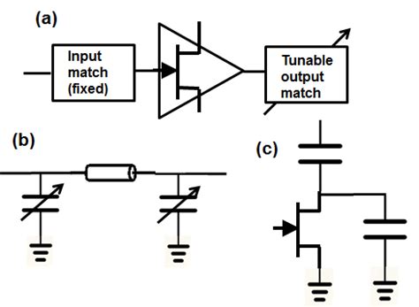
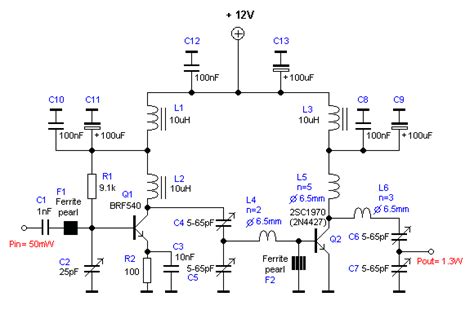
The third step in designing an RF amplifier is to design the input and output matching networks. The matching networks are used to transform the input and output impedances of the transistor to the desired values, typically 50 ohms, to maximize power transfer and minimize signal reflections.
Impedance Matching Techniques
There are several techniques used for impedance matching in RF amplifier design, including:
- Lumped element matching using inductors and capacitors
- Transmission line matching using microstrip or stripline
- Stub matching using open or short circuit stubs
- Transformer matching using coupled inductors
The choice of matching technique depends on factors such as the frequency range, bandwidth, and physical size of the amplifier.
Matching Network Design
The design of the matching networks involves the following steps:
- Determine the input and output impedances of the transistor at the desired frequency and output power.
- Calculate the required impedance transformation ratio and quality factor (Q) for each matching network.
- Select the appropriate matching technique and components based on the calculated values and design constraints.
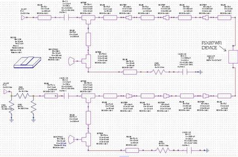
- Simulate and optimize the matching networks using RF circuit simulation software, such as Keysight ADS or NI AWR.
- Fabricate and test the matching networks to verify their performance.

Step 4: Stabilize the Amplifier
The fourth step in designing an RF amplifier is to ensure its stability across the entire operating frequency range and output power range. Instability in an RF amplifier can cause oscillation, which can damage the transistor and degrade the signal quality.
Stability Analysis
Stability analysis involves calculating the stability factors, such as the Rollett stability factor (K) and the stability measure (B1), using the S-parameters of the transistor and the matching networks. A stable amplifier should have K > 1 and B1 > 0 at all frequencies.
Stabilization Techniques
If the stability analysis shows that the amplifier is potentially unstable, several techniques can be used to stabilize it, such as:
- Adding a resistive loading to the input or output of the transistor
- Using a feedback network to reduce the gain at high frequencies
- Incorporating a Low-pass filter to suppress high-frequency oscillations
- Using a balanced or push-pull configuration to cancel out even-order harmonics
The choice of stabilization technique depends on the specific cause of instability and the design constraints of the amplifier.
Step 5: Optimize the Performance
The final step in designing an RF amplifier is to optimize its performance in terms of gain, efficiency, linearity, and other key parameters. This involves iterative simulations and measurements to fine-tune the design and achieve the desired specifications.
Performance Metrics
Some of the key performance metrics to optimize in an RF amplifier design are:
- Gain and gain flatness across the operating frequency range
- Efficiency and power-added efficiency (PAE) at the desired output power
- Linearity and intermodulation distortion (IMD) under modulated signal conditions
- Noise figure and signal-to-noise ratio (SNR)
- Input and output return loss and isolation
These metrics can be measured using various test equipment, such as vector network analyzers, spectrum analyzers, and power meters.
Optimization Techniques
Several techniques can be used to optimize the performance of an RF amplifier, such as:
- Adjusting the bias point and quiescent current of the transistor
- Fine-tuning the matching networks and stabilization circuits
- Using advanced linearization techniques, such as predistortion and feedforward
- Incorporating power control and temperature compensation circuits
- Using multi-stage or cascaded amplifier configurations
The choice of optimization technique depends on the specific performance goals and design constraints of the amplifier.
Frequently Asked Questions (FAQ)
1. What is the difference between an RF amplifier and a regular amplifier?
An RF amplifier is specifically designed to operate at high frequencies, typically in the range of megahertz (MHz) to gigahertz (GHz), while a regular amplifier operates at lower frequencies, such as audio or video frequencies. RF amplifiers also have more stringent requirements in terms of impedance matching, stability, and linearity compared to regular amplifiers.
2. What are the most common types of transistors used in RF amplifier design?
The most common types of transistors used in RF amplifier design are:
- Bipolar Junction Transistors (BJTs)
- Field-Effect Transistors (FETs), including MOSFETs and JFETs
- High Electron Mobility Transistors (HEMTs)
- Heterojunction Bipolar Transistors (HBTs)
Each type of transistor has its own advantages and disadvantages in terms of gain, efficiency, linearity, and cost.
3. What is the purpose of impedance matching in RF amplifier design?
The purpose of impedance matching in RF amplifier design is to maximize power transfer and minimize signal reflections between the transistor and the input/output ports. By transforming the input and output impedances of the transistor to the desired values, typically 50 ohms, the matching networks ensure that most of the available power is delivered to the load and that the signal integrity is maintained.
4. How can I ensure the stability of an RF amplifier?
To ensure the stability of an RF amplifier, you can follow these steps:
- Perform a stability analysis using the S-parameters of the transistor and the matching networks.
- Calculate the stability factors, such as the Rollett stability factor (K) and the stability measure (B1), at all frequencies.
- If the amplifier is potentially unstable (K < 1 or B1 < 0), apply appropriate stabilization techniques, such as resistive loading, feedback networks, low-pass filters, or balanced configurations.
- Simulate and measure the stability of the amplifier under various operating conditions to verify its robustness.
5. What are some advanced techniques for optimizing the performance of an RF amplifier?
Some advanced techniques for optimizing the performance of an RF amplifier include:
- Predistortion: A technique that compensates for the nonlinearity of the amplifier by applying an inverse distortion to the input signal.
- Feedforward: A technique that cancels out the distortion and noise generated by the amplifier by subtracting a scaled version of the output from the input signal.
- Envelope tracking: A technique that dynamically adjusts the supply voltage of the amplifier based on the envelope of the input signal to improve efficiency and linearity.
- Digital predistortion (DPD): A technique that uses digital signal processing (DSP) to pre-compensate for the nonlinearity of the amplifier in the digital domain.
These techniques can significantly improve the performance of an RF amplifier, but they also increase the complexity and cost of the design.
Conclusion
Designing an efficient and reliable RF amplifier involves a systematic approach that considers the specifications, transistor selection, matching networks, stability, and performance optimization. By following the five steps outlined in this article, you can create an RF amplifier that meets the specific requirements of your application and delivers superior performance in terms of gain, efficiency, linearity, and stability.
However, RF amplifier design is a complex and iterative process that requires a deep understanding of the underlying principles and techniques. It also involves the use of advanced simulation and measurement tools to verify and optimize the design. Therefore, it is important to have a solid foundation in RF electronics and to keep up with the latest developments and best practices in the field.
With the increasing demand for wireless communication systems and the emergence of new technologies, such as 5G and IoT, the importance of RF amplifier design will only continue to grow. By mastering the art and science of RF amplifier design, you can contribute to the development of next-generation wireless solutions that will shape the future of communication and connectivity.

No responses yet