Introduction to the Raspberry Pi Pico
The Raspberry Pi Pico is a microcontroller board developed by the Raspberry Pi Foundation. It is based on the RP2040 microcontroller chip, which features a dual-core ARM Cortex-M0+ processor running at up to 133 MHz. The board is designed to be easy to use, with a simple pinout and a wide range of software support, including MicroPython and C/C++.
Key Features of the Raspberry Pi Pico
- Dual-core ARM Cortex-M0+ processor running at up to 133 MHz
- 264KB of SRAM
- 2MB of flash memory
- 26 multi-function GPIO pins
- 2x SPI, 2x I2C, 2x UART, 3x 12-bit ADC, 16x PWM channels
- USB 1.1 with device and host support
- Low-power sleep and dormant modes
- Drag-and-drop programming using mass storage over USB
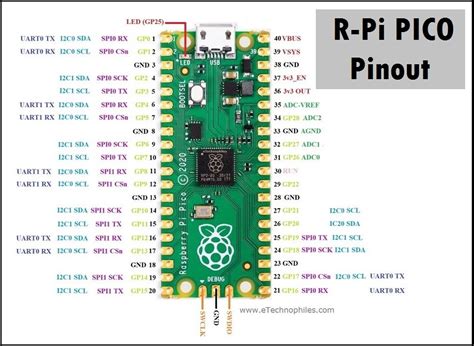
Pico Pinout Overview
The Raspberry Pi Pico features a 40-pin GPIO header, which provides access to the board’s various inputs, outputs, and communication interfaces. The pinout is designed to be simple and easy to use, with clearly labeled pins and a logical layout.
GPIO Pins
The Pico has 26 multi-function GPIO pins, which can be used for digital input and output, as well as various communication protocols. Each pin can be configured as an input or output, and can be used with internal pull-up or pull-down resistors.
| Pin | Function |
|---|---|
| GP0-GP22 | General-purpose input/output |
| GP26-GP28 | General-purpose input/output |
Power and Ground Pins
The Pico has several power and ground pins, which provide access to the board’s 3.3V supply and ground connections.
| Pin | Function |
|---|---|
| VSYS | System voltage input (1.8-5.5V) |
| 3V3 | 3.3V output (max. 300mA) |
| GND | Ground |
Communication Interfaces
The Pico supports a range of communication interfaces, including SPI, I2C, and UART. These interfaces allow the board to communicate with external devices, such as sensors, displays, and other microcontrollers.
SPI (Serial Peripheral Interface)
SPI is a synchronous serial communication interface that allows the Pico to communicate with external devices at high speeds. The Pico has two SPI interfaces, which can be used simultaneously.
| Pin | Function |
|---|---|
| GP2 | SPI0 TX |
| GP3 | SPI0 RX |
| GP4 | SPI0 SCK |
| GP5 | SPI0 CSn |
| GP10 | SPI1 TX |
| GP11 | SPI1 RX |
| GP12 | SPI1 SCK |
| GP13 | SPI1 CSn |
I2C (Inter-Integrated Circuit)
I2C is a synchronous serial communication interface that allows the Pico to communicate with external devices using a simple two-wire interface. The Pico has two I2C interfaces, which can be used simultaneously.
| Pin | Function |
|---|---|
| GP6 | I2C0 SDA |
| GP7 | I2C0 SCL |
| GP14 | I2C1 SDA |
| GP15 | I2C1 SCL |
UART (Universal Asynchronous Receiver-Transmitter)
UART is an asynchronous serial communication interface that allows the Pico to communicate with external devices using a simple two-wire interface. The Pico has two UART interfaces, which can be used simultaneously.
| Pin | Function |
|---|---|
| GP0 | UART0 TX |
| GP1 | UART0 RX |
| GP8 | UART1 TX |
| GP9 | UART1 RX |
Analog Input
The Pico has three 12-bit analog-to-digital converters (ADCs), which can be used to measure analog voltages on the board’s GPIO pins. The ADCs have a resolution of 12 bits and a maximum sampling rate of 500 ksps.
| Pin | Function |
|---|---|
| GP26 | ADC0 |
| GP27 | ADC1 |
| GP28 | ADC2 |
PWM Output
The Pico has 16 pulse-width modulation (PWM) channels, which can be used to generate analog-like output signals. PWM can be used to control the brightness of LEDs, the speed of motors, and other applications that require variable output.
| Pin | Function |
|---|---|
| GP0-GP15 | PWM0-PWM15 |

Using the Pico Pinout
Now that we have a basic understanding of the Pico’s pinout, let’s explore some examples of how it can be used in various applications.
Example 1: Controlling an LED
One of the simplest ways to use the Pico’s GPIO pins is to control an LED. To do this, we can connect an LED to one of the GPIO pins and use the Pico’s built-in PWM functionality to control its brightness.
- Connect the anode (positive) of the LED to a GPIO pin (e.g., GP0) through a current-limiting resistor (e.g., 220 ohms).
- Connect the cathode (negative) of the LED to ground (GND).
- Use the following MicroPython code to control the LED’s brightness:
from machine import Pin, PWM
from time import sleep

led = PWM(Pin(0))

while True:
    for duty in range(0, 65536, 1024):
        led.duty_u16(duty)
        sleep(0.01)
    for duty in range(65536, 0, -1024):
        led.duty_u16(duty)
        sleep(0.01)
This code creates a PWM object on GPIO pin 0 and uses a loop to gradually increase and decrease the LED’s brightness using the duty_u16() method.
Example 2: Reading an Analog Sensor
The Pico’s ADC functionality can be used to read analog sensors, such as temperature sensors or potentiometers. In this example, we’ll use a simple potentiometer to control the brightness of an LED.
- Connect the potentiometer’s outer pins to 3.3V and ground, and connect the middle pin to one of the Pico’s ADC pins (e.g., GP26).
- Connect an LED to a GPIO pin as described in Example 1.
- Use the following MicroPython code to read the potentiometer value and control the LED’s brightness:
from machine import Pin, PWM, ADC
from time import sleep

led = PWM(Pin(0))
pot = ADC(26)

while True:
    duty = pot.read_u16()
    led.duty_u16(duty)
    sleep(0.01)
This code creates an ADC object on GPIO pin 26 and uses a loop to read the potentiometer value and set the LED’s brightness accordingly using the duty_u16() method.
Example 3: Communicating with an External Device
The Pico’s communication interfaces can be used to communicate with external devices, such as sensors or other microcontrollers. In this example, we’ll use the Pico’s I2C interface to read data from a simple temperature and humidity sensor (e.g., the DHT11).
- Connect the DHT11 sensor to the Pico’s I2C pins (e.g., GP6 for SDA and GP7 for SCL) and power it from the Pico’s 3.3V and ground pins.
- Use the following MicroPython code to read data from the sensor:
from machine import Pin, I2C
from time import sleep
from dht import DHT11

i2c = I2C(0, sda=Pin(6), scl=Pin(7))
dht = DHT11(Pin(6))

while True:
    dht.measure()
    temp = dht.temperature()
    hum = dht.humidity()
    print(f"Temperature: {temp}°C, Humidity: {hum}%")
    sleep(2)
This code creates an I2C object on GPIO pins 6 and 7, and uses the DHT11 library to read temperature and humidity data from the sensor every 2 seconds.

Conclusion
The Raspberry Pi Pico’s pinout is a versatile and powerful tool for a wide range of electronics projects. Its multi-function GPIO pins, communication interfaces, and analog input and output capabilities make it an ideal choice for hobbyists, students, and professionals alike. By understanding the Pico’s pinout and exploring some basic examples, you can start creating your own projects and unleash the full potential of this amazing microcontroller board.

Frequently Asked Questions (FAQ)
-
What is the Raspberry Pi Pico?
The Raspberry Pi Pico is a low-cost, high-performance microcontroller board based on the RP2040 microcontroller chip. It is designed for a wide range of applications, from simple projects to complex embedded systems. -
What programming languages can be used with the Pico?
The Pico supports several programming languages, including MicroPython and C/C++. It also has a built-in bootloader that allows for drag-and-drop programming using mass storage over USB. -
How many GPIO pins does the Pico have?
The Pico has 26 multi-function GPIO pins, which can be used for digital input and output, as well as various communication protocols such as SPI, I2C, and UART. -
Can the Pico be powered directly from a battery?
Yes, the Pico can be powered from a wide range of voltage sources (1.8-5.5V) through its VSYS pin. This allows it to be powered directly from batteries or other external power supplies. -
What is the maximum current that the Pico’s GPIO pins can supply?
Each of the Pico’s GPIO pins can supply a maximum current of 12mA. However, the total current drawn from all GPIO pins should not exceed 50mA to avoid damaging the board.
No responses yet