Introduction to Signal Amplifiers
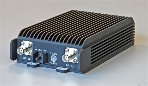
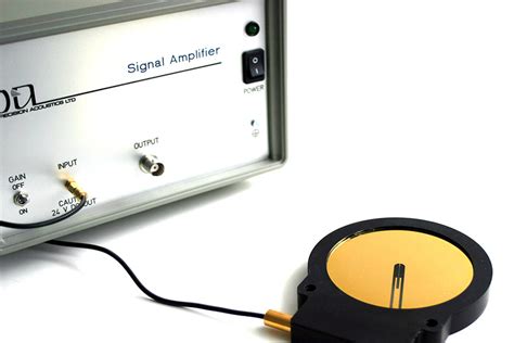
A signal amplifier is an electronic device that increases the power, voltage, or current of a signal. It is an essential component in various applications, such as audio systems, telecommunications, and scientific instrumentation. The primary purpose of a signal amplifier is to boost weak signals to a level that can be easily processed, transmitted, or recorded without introducing significant noise or distortion.
Types of Signal Amplifiers
There are several types of signal amplifiers, each designed for specific applications and signal characteristics. Some common types include:
-
Voltage Amplifiers: These amplifiers increase the voltage level of a signal while maintaining a constant current. They are commonly used in audio systems and oscilloscopes.
-
Current Amplifiers: These amplifiers increase the current level of a signal while keeping the voltage constant. They are often used in power amplifiers and current-to-voltage converters.
-
Power Amplifiers: These amplifiers increase both the voltage and current of a signal, resulting in an overall increase in power. They are used in audio systems, radio transmitters, and other high-power applications.
-
Operational Amplifiers (Op-amps): These are high-gain, multi-stage amplifiers that can be configured for various applications, such as signal conditioning, filtering, and mathematical operations.
Key Parameters of Signal Amplifiers
When designing or selecting a signal amplifier, several key parameters must be considered:
-
Gain: The ratio of the output signal level to the input signal level, usually expressed in decibels (dB).
-
Bandwidth: The range of frequencies over which the amplifier can effectively amplify the signal without significant attenuation or distortion.
-
Noise: The unwanted random fluctuations introduced by the amplifier, which can degrade the signal-to-noise ratio (SNR) of the output signal.
-
Distortion: The deviation of the output signal from a perfect replica of the input signal, often caused by non-linear behavior of the amplifier components.
-
Input and Output Impedance: The effective resistance of the amplifier’s input and output ports, which affects the transfer of signal power between the amplifier and connected devices.
Designing a Signal Amplification Device
Step 1: Determine the Application Requirements
Before designing a signal amplifier, it is crucial to identify the specific requirements of the intended application. Some key factors to consider include:
- Input and output signal characteristics (voltage, current, frequency range)
- Required gain and bandwidth
- Acceptable levels of noise and distortion
- Power supply constraints (voltage, current, efficiency)
- Physical size and environmental conditions
Step 2: Select the Appropriate Amplifier Topology
Based on the application requirements, choose an amplifier topology that best suits your needs. Some common topologies include:
-
Common-Emitter (CE) Amplifier: A single-stage transistor amplifier that provides moderate gain and wide bandwidth. It is simple to design and implement but has limited input and output impedance control.
-
Common-Collector (CC) Amplifier: Also known as an emitter follower, this single-stage transistor amplifier provides high input impedance, low output impedance, and unity gain. It is often used as a buffer stage between high-impedance sources and low-impedance loads.
-
Common-Base (CB) Amplifier: A single-stage transistor amplifier that offers high voltage gain and wide bandwidth but has low input impedance. It is less commonly used than CE and CC amplifiers.
-
Differential Amplifier: A two-stage amplifier that amplifies the difference between two input signals while rejecting common-mode noise. It is widely used in op-amps and balanced signal processing.
-
Push-Pull Amplifier: A power amplifier that uses complementary transistors to amplify both the positive and negative half-cycles of the input signal. It provides high efficiency and power output but requires careful biasing and matching of the transistors.
Step 3: Design the Amplifier Circuit
Once you have selected the appropriate amplifier topology, you can begin designing the circuit. This process involves the following sub-steps:
-
Choose the active components: Select transistors or op-amps that meet the required gain, bandwidth, noise, and power specifications. Consider factors such as the maximum collector current, breakdown voltage, and transition frequency (ft) for transistors, or the gain-bandwidth product (GBP), slew rate, and input/output impedances for op-amps.
-
Determine the biasing network: Design a biasing network that sets the appropriate DC operating point for the active components. This typically involves selecting resistor values to establish the desired collector current and voltage for transistors or the input and output offset voltages for op-amps.
-
Calculate the component values: Use circuit analysis techniques, such as Kirchhoff’s laws and small-signal models, to determine the values of resistors, capacitors, and inductors needed to achieve the desired gain, bandwidth, and impedance characteristics. Consider factors such as load impedance, input and output coupling, and frequency compensation.
-
Simulate the circuit: Use circuit simulation software, such as SPICE or Multisim, to verify the performance of the designed amplifier. Analyze the frequency response, transient response, and noise characteristics to ensure they meet the application requirements. Make adjustments to the component values as needed.
Step 4: Build and Test the Prototype
After finalizing the circuit design, construct a prototype of the signal amplifier using the selected components. Follow best practices for circuit board layout, grounding, and shielding to minimize noise and interference. Test the prototype under various operating conditions to validate its performance. Measure key parameters such as gain, bandwidth, noise, and distortion, and compare them to the design specifications. Make any necessary adjustments or optimizations based on the test results.
Step 5: Optimize and Finalize the Design
Based on the prototype testing results, refine the amplifier design to improve its performance, reliability, and cost-effectiveness. Consider the following optimization techniques:
-
Feedback and compensation: Implement negative feedback to reduce distortion, improve linearity, and stabilize the gain and bandwidth of the amplifier. Use frequency compensation techniques, such as lead-lag networks or Miller compensation, to ensure stable operation and prevent oscillation.
-
Noise reduction: Minimize noise by selecting low-noise components, optimizing the circuit layout, and using shielding and grounding techniques. Consider using balanced signal paths or differential amplifiers to reject common-mode noise.
-
Power optimization: Improve the power efficiency of the amplifier by using class-AB or class-D output stages, which reduce the quiescent current while maintaining high output power. Implement power supply decoupling and regulation to minimize supply-related noise and distortion.
-
Thermal management: Ensure proper heat dissipation from the active components to prevent thermal runaway and maintain long-term reliability. Use heatsinks, thermal pads, or fans as needed, and consider the thermal resistance and power dissipation of the components when selecting the packaging and layout.

Common Applications of Signal Amplifiers
Signal amplifiers are used in a wide range of applications across various industries. Some common applications include:
Audio Systems
In audio systems, signal amplifiers are used to increase the power of low-level audio signals from sources such as microphones, guitars, and CD players. They drive loudspeakers or headphones to produce sound at the desired volume and quality. Audio amplifiers are designed to provide high gain, wide bandwidth, and low distortion to faithfully reproduce the original audio signal.
| Application | Amplifier Type | Typical Power Output |
|---|---|---|
| Headphones | Op-amp or IC | 10 mW – 1 W |
| Home stereo | Class-AB or D | 10 W – 200 W |
| Car audio | Class-AB or D | 10 W – 1000 W |
| Live sound | Class-AB or D | 100 W – 10,000 W |
Telecommunications
In telecommunications systems, signal amplifiers are used to compensate for the attenuation and loss of signals transmitted over long distances. They are employed in various stages of the communication chain, such as:
-
Preamplifiers: These amplifiers are used to boost weak signals from antennas or sensors before they are processed by the main receiver circuitry. They are designed for low noise and high sensitivity to maximize the signal-to-noise ratio (SNR).
-
Line amplifiers: These amplifiers are used to periodically boost the signal level along a transmission line to overcome cable losses. They are designed for high gain, wide bandwidth, and low distortion to maintain signal integrity over long distances.
-
Power amplifiers: These amplifiers are used in the final stage of transmitters to increase the power of the modulated signal before it is sent to the antenna. They are designed for high efficiency, linearity, and power output to minimize distortion and maximize the transmission range.
Scientific Instrumentation
In scientific instrumentation, signal amplifiers are used to condition and process signals from sensors, transducers, and detectors. They are employed in various applications, such as:
-
Biomedical instrumentation: Amplifiers are used to measure and record biological signals, such as electrocardiograms (ECG), electroencephalograms (EEG), and electromyograms (EMG). They are designed for high input impedance, low noise, and precise gain control to accurately capture the small-amplitude signals generated by the body.
-
Optical instrumentation: Amplifiers are used to process signals from photodetectors, such as photodiodes and photomultiplier tubes, in applications like spectroscopy, imaging, and fiber-optic sensing. They are designed for wide bandwidth, low noise, and high sensitivity to detect weak optical signals.
-
Environmental monitoring: Amplifiers are used to condition signals from sensors that measure various environmental parameters, such as temperature, humidity, pressure, and gas concentration. They are designed for high accuracy, stability, and robustness to operate reliably in harsh environments.

Frequently Asked Questions (FAQ)
-
What is the difference between a voltage amplifier and a current amplifier?
A voltage amplifier increases the voltage level of a signal while maintaining a constant current, whereas a current amplifier increases the current level of a signal while keeping the voltage constant. Voltage amplifiers are commonly used in applications that require high input impedance and low output impedance, such as audio systems and oscilloscopes. Current amplifiers are often used in applications that require high output current, such as power amplifiers and current-to-voltage converters. -
What is the purpose of biasing in a transistor amplifier?
Biasing is the process of setting the appropriate DC operating point for a transistor amplifier. It involves establishing the desired collector current and voltage to ensure that the transistor operates in the linear region and provides the required gain and bandwidth. Proper biasing is essential for maintaining the stability, linearity, and efficiency of the amplifier. -
How does negative feedback improve the performance of an amplifier?
Negative feedback is a technique where a portion of the output signal is fed back to the input of the amplifier, out of phase with the input signal. This reduces the overall gain of the amplifier but improves its performance in several ways. Negative feedback reduces distortion by canceling out non-linearities in the amplifier’s transfer function. It also stabilizes the gain and bandwidth of the amplifier, making it less sensitive to variations in component values and operating conditions. Additionally, negative feedback can improve the input and output impedance characteristics of the amplifier. -
What is the significance of the gain-bandwidth product (GBP) in op-amps?
The gain-bandwidth product (GBP) is a key parameter that characterizes the performance of an operational amplifier (op-amp). It represents the product of the open-loop gain and the frequency at which the gain drops to unity (0 dB). The GBP is a constant for a given op-amp and sets a trade-off between the achievable gain and bandwidth. For example, if an op-amp has a GBP of 10 MHz, it can provide a gain of 100 (40 dB) up to a bandwidth of 100 kHz, or a gain of 10 (20 dB) up to a bandwidth of 1 MHz. When designing an amplifier with an op-amp, the GBP must be considered to ensure that the desired gain and bandwidth can be achieved simultaneously. -
What are some common techniques for reducing noise in signal amplifiers?
Noise is an unwanted random fluctuation that can degrade the performance of signal amplifiers. Several techniques can be employed to reduce noise in amplifier designs: -
Use low-noise components, such as transistors with low base resistance and op-amps with low input noise voltage and current.
- Optimize the circuit layout to minimize the pickup of external noise sources, such as power supply ripple and electromagnetic interference (EMI).
- Use shielding and grounding techniques to create a low-impedance path for noise currents and prevent them from coupling into the signal path.
- Implement balanced signal paths or differential amplifiers to reject common-mode noise, which appears equally on both signal lines.
- Use filtering techniques, such as low-pass, high-pass, or band-pass filters, to selectively attenuate noise outside the desired signal bandwidth.
- Employ power supply decoupling and regulation to minimize the effect of supply-related noise on the amplifier’s performance.
By understanding and applying these noise reduction techniques, designers can create signal amplifiers with improved signal-to-noise ratio (SNR) and overall performance.

Conclusion
Designing a signal amplification device involves a systematic approach that considers the application requirements, amplifier topology, circuit design, and optimization techniques. By following the steps outlined in this article, engineers and hobbyists can create custom signal amplifiers that meet the specific needs of their projects.
Key considerations in the design process include selecting the appropriate active components, determining the biasing network, calculating the component values, simulating the circuit, and optimizing the design for gain, bandwidth, noise, distortion, and power efficiency. Additionally, proper layout, grounding, and shielding techniques must be employed to minimize noise and interference.
Signal amplifiers find widespread use in various applications, such as audio systems, telecommunications, and scientific instrumentation. By understanding the principles and techniques involved in signal amplifier design, engineers can create robust and high-performance solutions that enable the effective processing, transmission, and recording of signals across multiple domains.
As technology advances, new amplifier topologies, components, and design tools will continue to emerge, offering opportunities for further improvement and innovation in signal amplification devices. By staying up-to-date with the latest developments and best practices, designers can push the boundaries of what is possible in terms of gain, bandwidth, noise, and efficiency, ultimately enabling new applications and enhancing the performance of existing systems.

No responses yet