Introduction to Quarter-Wave Transformers
A quarter-wave transformer (QWT) is a type of impedance matching device used in radio frequency (RF) and microwave circuits to match the impedance of a load to the characteristic impedance of a transmission line. The QWT is a simple yet effective solution for impedance matching, especially when dealing with real and reactive loads. By properly designing a QWT, engineers can optimize power transfer, minimize reflections, and improve overall system performance.
What is a Quarter-Wave Transformer?
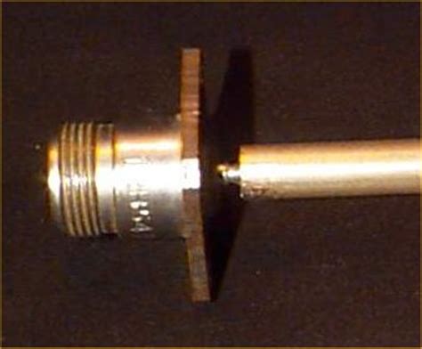
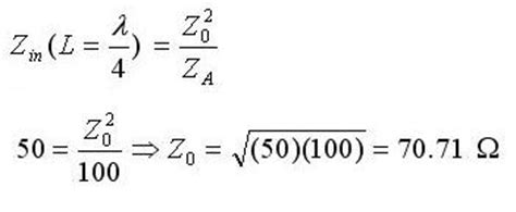
A quarter-wave transformer is a transmission line segment with a specific characteristic impedance (ZQWT) and a length equal to one-quarter of the wavelength (λ/4) at the operating frequency. The QWT is placed between the source (with impedance Z0) and the load (with impedance ZL) to transform the load impedance to match the source impedance.
The characteristic impedance of the QWT is calculated using the following formula:
ZQWT = √(Z0 × ZL)
where:
– ZQWT is the characteristic impedance of the quarter-wave transformer
– Z0 is the characteristic impedance of the source transmission line
– ZL is the load impedance
Benefits of Using Quarter-Wave Transformers
Quarter-wave transformers offer several advantages in RF and microwave circuit design:
- Simplicity: QWTs are easy to design and implement, requiring only a transmission line segment with the appropriate characteristic impedance and length.
- Bandwidth: Although QWTs are narrowband devices, they provide a good match over a relatively wide bandwidth compared to other impedance matching techniques, such as L-networks or stub matching.
- Low loss: QWTs have inherently low insertion loss, as they are composed of a single transmission line segment without any lumped elements or discontinuities.
- Compact size: At higher frequencies, the physical length of a QWT becomes smaller, making it suitable for compact circuit designs.
Designing Quarter-Wave Transformers for Real Loads
When designing a QWT for a real load, the load impedance is purely resistive (ZL = RL). In this case, the characteristic impedance of the QWT is calculated as follows:
ZQWT = √(Z0 × RL)
Step-by-Step Design Process for Real Loads
- Determine the operating frequency (f) and the corresponding wavelength (λ) in the transmission line medium.
- Calculate the physical length of the QWT (l) using the following formula:
l = λ / 4 - Select a suitable transmission line type (e.g., microstrip, stripline, coaxial) based on the circuit requirements and substrate properties.
- Calculate the characteristic impedance of the QWT using the formula:
ZQWT = √(Z0 × RL) - Design the transmission line segment with the calculated characteristic impedance and length using the appropriate design equations or software tools.
Example: Designing a QWT for a 50 Ω Real Load
Let’s consider an example where we need to design a QWT to match a 50 Ω source impedance to a 100 Ω real load at a frequency of 2 GHz. The transmission line medium is a microstrip on a Rogers RO4003C substrate (εr = 3.55, h = 0.813 mm).
-
Operating frequency (f) = 2 GHz
Wavelength (λ) in the microstrip medium:
λ = c / (f × √εeff)
where c is the speed of light, and εeff is the effective dielectric constant of the microstrip. For this example, let’s assume εeff = 2.8.
λ = 3 × 10⁸ m/s / (2 × 10⁹ Hz × √2.8) ≈ 89.8 mm -
Physical length of the QWT (l):
l = λ / 4 ≈ 22.5 mm -
Transmission line type: microstrip on Rogers RO4003C substrate
-
Characteristic impedance of the QWT:
ZQWT = √(50 Ω × 100 Ω) ≈ 70.7 Ω -
Design the microstrip transmission line segment with a characteristic impedance of 70.7 Ω and a length of 22.5 mm using microstrip design equations or software tools.
| Parameter | Value |
|---|---|
| Operating frequency (f) | 2 GHz |
| Source impedance (Z0) | 50 Ω |
| Load impedance (RL) | 100 Ω |
| Wavelength (λ) | 89.8 mm |
| QWT length (l) | 22.5 mm |
| QWT characteristic impedance (ZQWT) | 70.7 Ω |

Designing Quarter-Wave Transformers for Reactive Loads
When designing a QWT for a reactive load, the load impedance has both real and imaginary components (ZL = RL + jXL). In this case, the design process becomes more complex, as the QWT alone cannot provide a perfect match. However, by combining the QWT with an additional reactive component, such as a series or parallel capacitor or inductor, a good match can be achieved.
Step-by-Step Design Process for Reactive Loads
- Determine the operating frequency (f) and the corresponding wavelength (λ) in the transmission line medium.
- Calculate the physical length of the QWT (l) using the following formula:
l = λ / 4 - Select a suitable transmission line type (e.g., microstrip, stripline, coaxial) based on the circuit requirements and substrate properties.
- Calculate the real part of the load impedance (RL) and the imaginary part of the load impedance (XL).
- Design a matching network using a reactive component (series or parallel capacitor or inductor) to cancel out the imaginary part of the load impedance. The resulting impedance should be purely real (RM).
- Calculate the characteristic impedance of the QWT using the formula:
ZQWT = √(Z0 × RM) - Design the transmission line segment with the calculated characteristic impedance and length using the appropriate design equations or software tools.
Example: Designing a QWT for a 50 + j30 Ω Reactive Load
Let’s consider an example where we need to design a QWT to match a 50 Ω source impedance to a 50 + j30 Ω reactive load at a frequency of 1.5 GHz. The transmission line medium is a microstrip on an FR4 substrate (εr = 4.4, h = 1.6 mm).
-
Operating frequency (f) = 1.5 GHz
Wavelength (λ) in the microstrip medium:
λ = c / (f × √εeff)
where c is the speed of light, and εeff is the effective dielectric constant of the microstrip. For this example, let’s assume εeff = 3.2.
λ = 3 × 10⁸ m/s / (1.5 × 10⁹ Hz × √3.2) ≈ 111.8 mm -
Physical length of the QWT (l):
l = λ / 4 ≈ 28.0 mm -
Transmission line type: microstrip on FR4 substrate
-
Real part of the load impedance (RL) = 50 Ω
Imaginary part of the load impedance (XL) = 30 Ω -
Design a matching network using a series capacitor to cancel out the imaginary part of the load impedance:
C = 1 / (2π × f × XL) ≈ 3.5 pF
The resulting matched impedance (RM) = 50 Ω -
Characteristic impedance of the QWT:
ZQWT = √(50 Ω × 50 Ω) ≈ 50 Ω -
Design the microstrip transmission line segment with a characteristic impedance of 50 Ω and a length of 28.0 mm using microstrip design equations or software tools.
| Parameter | Value |
|---|---|
| Operating frequency (f) | 1.5 GHz |
| Source impedance (Z0) | 50 Ω |
| Load impedance (ZL) | 50 + j30 Ω |
| Wavelength (λ) | 111.8 mm |
| QWT length (l) | 28.0 mm |
| Matching capacitor (C) | 3.5 pF |
| Matched impedance (RM) | 50 Ω |
| QWT characteristic impedance (ZQWT) | 50 Ω |

Bandwidth Considerations for Quarter-Wave Transformers
Quarter-wave transformers are inherently narrowband devices, providing a good match only over a limited frequency range around the design frequency. The bandwidth of a QWT depends on the ratio of the load impedance to the source impedance and the acceptable level of mismatch.
Bandwidth Calculation
The fractional bandwidth (FBW) of a QWT can be estimated using the following formula:
FBW ≈ (4 / π) × (ZL / Z0 – 1) / (ZL / Z0 + 1)
where:
– FBW is the fractional bandwidth
– ZL is the load impedance
– Z0 is the source impedance
For example, if we have a 50 Ω source impedance and a 100 Ω load impedance, the fractional bandwidth would be:
FBW ≈ (4 / π) × (100 Ω / 50 Ω – 1) / (100 Ω / 50 Ω + 1) ≈ 0.42 or 42%
This means that the QWT would provide a good match (with a certain level of acceptable mismatch) over a frequency range of approximately ±21% around the design frequency.
Improving Bandwidth
To improve the bandwidth of a QWT, several techniques can be employed:
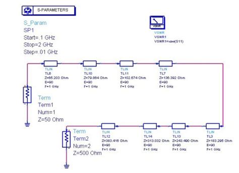
- Multi-section transformers: By cascading multiple QWT sections with different characteristic impedances, the bandwidth can be increased at the cost of increased circuit complexity and size.
- Tapered transformers: Gradually varying the characteristic impedance of the transformer along its length can help improve the bandwidth compared to a single-section QWT.
- Combining with other matching techniques: QWTs can be used in conjunction with other matching techniques, such as stub matching or L-networks, to achieve a wider bandwidth.

Practical Considerations for Implementing Quarter-Wave Transformers
When implementing QWTs in practical RF and microwave circuits, several factors should be considered to ensure optimal performance:
- Transmission Line Losses: At higher frequencies, transmission line losses can become significant, affecting the performance of the QWT. It is essential to account for these losses in the design process and choose low-loss substrate materials when possible.
- Discontinuities and parasitics: Discontinuities in the transmission line, such as bends, junctions, or connectors, can introduce parasitic reactances that affect the matching performance. Careful layout and design techniques should be employed to minimize these effects.
- Substrate selection: The choice of substrate material and thickness plays a crucial role in the performance of the QWT. Factors such as dielectric constant, loss tangent, and thermal stability should be considered when selecting a substrate.
- Manufacturing tolerances: Fabrication tolerances can lead to variations in the characteristic impedance and length of the QWT, affecting its performance. It is important to account for these tolerances in the design process and specify appropriate manufacturing guidelines.
- Power handling: The power handling capability of the QWT should be considered, especially in high-power applications. The transmission line dimensions and substrate material should be chosen to ensure adequate power handling without causing thermal or breakdown issues.
Conclusion
Quarter-wave transformers are an essential tool for impedance matching in RF and microwave circuits, particularly when dealing with real and reactive loads. By understanding the design principles and practical considerations associated with QWTs, engineers can effectively implement these devices to optimize power transfer, minimize reflections, and improve overall system performance.
While QWTs are inherently narrowband, techniques such as multi-section transformers, tapered transformers, and combination with other matching methods can be employed to increase the bandwidth. Additionally, careful consideration of transmission line losses, discontinuities, substrate selection, manufacturing tolerances, and power handling is necessary for successful implementation in practical circuits.
As the demand for high-performance RF and microwave systems continues to grow, the ability to design and implement effective impedance matching networks, such as quarter-wave transformers, will remain a critical skill for engineers in this field.
Frequently Asked Questions (FAQ)
-
What is the purpose of a quarter-wave transformer?
A quarter-wave transformer is used to match the impedance of a load to the characteristic impedance of a transmission line, ensuring maximum power transfer and minimizing reflections. -
How does a quarter-wave transformer work?
A quarter-wave transformer is a transmission line segment with a specific characteristic impedance and a length equal to one-quarter of the wavelength at the operating frequency. By placing this transformer between the source and the load, it effectively transforms the load impedance to match the source impedance. -
Can a quarter-wave transformer be used for both real and reactive loads?
Yes, quarter-wave transformers can be used for both real and reactive loads. However, when dealing with reactive loads, an additional reactive component (such as a series or parallel capacitor or inductor) is required to cancel out the imaginary part of the load impedance before applying the QWT. -
What are the limitations of quarter-wave transformers?
Quarter-wave transformers are inherently narrowband devices, providing a good match only over a limited frequency range around the design frequency. The bandwidth of a QWT depends on the ratio of the load impedance to the source impedance and the acceptable level of mismatch. -
What practical considerations should be taken into account when implementing quarter-wave transformers?
When implementing quarter-wave transformers in practical RF and microwave circuits, several factors should be considered, including transmission line losses, discontinuities and parasitics, substrate selection, manufacturing tolerances, and power handling capabilities. Addressing these factors is essential for ensuring optimal performance of the QWT in real-world applications.

No responses yet