Introduction to PWM Power Supplies
Pulse Width Modulation (PWM) is a technique used in power supply design to efficiently regulate voltage and current. PWM power supplies have become increasingly popular due to their high efficiency, fast response times, and ability to minimize power losses. In this article, we will delve into the fundamentals of PWM power supply design, discussing its working principles, components, and practical applications.
What is Pulse Width Modulation (PWM)?
Pulse Width Modulation is a method of controlling the average voltage and current delivered to a load by rapidly switching a power source on and off. By varying the duty cycle, which is the proportion of time the power is on versus off, the average voltage and current can be precisely regulated. PWM offers several advantages over linear regulation techniques, including:
- Higher efficiency
- Reduced heat dissipation
- Faster response times
- Smaller component sizes
Basic Components of a PWM Power Supply
A typical PWM power supply consists of several key components that work together to convert input power into a regulated output. These components include:
1. Power Switches
Power switches, usually MOSFETs or IGBTs, are responsible for rapidly turning the power on and off based on the PWM control signal. These switches must be capable of handling the required voltage and current levels while minimizing power losses during switching transitions.
2. Inductor
The inductor is a crucial component in a PWM power supply, as it stores energy during the on-time of the power switch and releases it to the load during the off-time. The inductor helps to smooth out the current ripple and maintain a continuous flow of current to the load.
3. Output Capacitor
The output capacitor is used to filter the voltage ripple caused by the switching action of the power supply. It helps to maintain a stable output voltage by providing a low-impedance path for high-frequency currents.
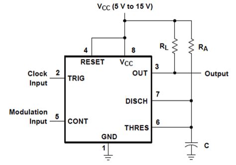
4. PWM Controller
The PWM controller generates the control signal that determines the duty cycle of the power switches. It monitors the output voltage and current, comparing them to a reference value and adjusting the duty cycle accordingly to maintain the desired output.
5. Feedback Network
The feedback network provides the necessary information to the PWM controller about the output voltage and current. It typically consists of voltage dividers, current sensors, and error amplifiers that compare the output values to the reference values.
PWM Control Techniques
There are several PWM control techniques used in power supply design, each with its own advantages and disadvantages. The most common techniques include:
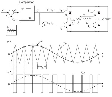
1. Voltage Mode Control
Voltage mode control is the simplest PWM control technique, where the output voltage is compared to a reference voltage, and the error signal is used to adjust the duty cycle of the power switches. This technique offers good line regulation but may suffer from poor load regulation and stability issues.
2. Current Mode Control
Current mode control uses the inductor current as an additional feedback signal, providing cycle-by-cycle current limiting and improved load regulation. This technique offers better stability and faster response times compared to voltage mode control.
3. Hysteretic Control
Hysteretic control, also known as bang-bang control, uses a comparator with hysteresis to directly control the power switches based on the output voltage. When the output voltage drops below a certain threshold, the power switch is turned on, and when it rises above another threshold, the switch is turned off. This technique offers excellent transient response but may result in variable switching frequency.

PWM Power Supply Topologies
PWM power supplies can be implemented using various topologies, each with its own characteristics and suitable applications. Some common topologies include:
1. Buck Converter
A buck converter, also known as a step-down converter, produces an output voltage lower than the input voltage. It is widely used in applications such as battery charging, DC motor control, and voltage regulation for digital circuits.
2. Boost Converter
A boost converter, or step-up converter, generates an output voltage higher than the input voltage. It is commonly used in applications such as LED drivers, solar power systems, and battery-powered devices.
3. Buck-Boost Converter
A buck-boost converter can produce an output voltage that is either higher or lower than the input voltage, making it versatile for a wide range of applications. It is often used in battery-powered devices, where the input voltage may vary over time.
4. Flyback Converter
A flyback converter is an isolated topology that uses a transformer to provide galvanic isolation between the input and output. It is commonly used in low-power applications, such as offline switching power supplies and battery chargers.
PWM Power Supply Design Considerations
When designing a PWM power supply, several key factors must be considered to ensure optimal performance, efficiency, and reliability. These factors include:
1. Input and Output Specifications
The input voltage range, output voltage, and maximum output current must be clearly defined to select the appropriate components and topology for the power supply.
2. Efficiency
High efficiency is crucial for minimizing power losses and heat generation. The choice of components, switching frequency, and control technique can greatly impact the overall efficiency of the power supply.
3. Stability
The power supply must be stable under all operating conditions, including line and load variations. Proper feedback compensation and control loop design are essential for maintaining stability.
4. Electromagnetic Compatibility (EMC)
PWM power supplies generate high-frequency noise due to the switching action of the power switches. Proper EMC design, including input and output filtering, shielding, and layout considerations, is necessary to minimize electromagnetic interference (EMI) and meet regulatory requirements.
5. Thermal Management
Efficient thermal management is crucial for ensuring the long-term reliability of the power supply. Proper heat sinking, airflow, and component selection can help to minimize temperature rise and prevent overheating.
Practical Applications of PWM Power Supplies
PWM power supplies find applications in a wide range of industries and products, including:
- Consumer electronics (smartphones, laptops, televisions)
- Industrial automation and control systems
- Automotive electronics (infotainment systems, lighting, motor control)
- Telecommunications and networking equipment
- Medical devices and instrumentation
Conclusion
PWM power supply design is a critical aspect of modern electronics, offering high efficiency, fast response times, and precise voltage and current regulation. By understanding the basic components, control techniques, and design considerations, engineers can develop optimized PWM power supplies for a wide range of applications. As technology continues to advance, PWM power supplies will play an increasingly important role in powering the devices and systems that shape our world.
Frequently Asked Questions (FAQ)
1. What is the main advantage of using PWM in power supply design?
The main advantage of using PWM in power supply design is its high efficiency. By rapidly switching the power on and off, PWM minimizes power losses and allows for smaller component sizes compared to linear regulation techniques.
2. What are the key components of a PWM power supply?
The key components of a PWM power supply include power switches (MOSFETs or IGBTs), an inductor, an output capacitor, a PWM controller, and a feedback network.
3. What is the difference between voltage mode control and current mode control in PWM?
Voltage mode control relies solely on the output voltage feedback to adjust the duty cycle, while current mode control uses both output voltage and inductor current feedback. Current mode control offers better load regulation and faster response times compared to voltage mode control.
4. What is the role of the inductor in a PWM power supply?
The inductor stores energy during the on-time of the power switch and releases it to the load during the off-time. It helps to smooth out the current ripple and maintain a continuous flow of current to the load.
5. What are some common applications of PWM power supplies?
PWM power supplies are used in a wide range of applications, including consumer electronics, industrial automation, automotive electronics, telecommunications, and medical devices. They are particularly well-suited for applications requiring high efficiency, fast response times, and precise voltage and current regulation.
Here’s a table summarizing the key differences between PWM control techniques:
| Control Technique | Advantages | Disadvantages |
|---|---|---|
| Voltage Mode | Simple implementation, good line regulation | Poor load regulation, stability issues |
| Current Mode | Cycle-by-cycle current limiting, improved load regulation, faster response times | More complex implementation, requires current sensing |
| Hysteretic | Excellent transient response, simple implementation | Variable switching frequency, higher output ripple |
No responses yet