How Does a Push-Pull Amplifier Work?
A push-pull amplifier consists of two transistors, one NPN and one PNP, that are connected in a complementary configuration. The input signal is split into two equal but opposite phases, which are then fed into the bases of the two transistors. The transistors amplify the signal and combine their outputs to produce a single, high-power output signal.
The NPN transistor amplifies the positive half of the input signal, while the PNP transistor amplifies the negative half. This configuration allows the amplifier to produce a larger output signal than either transistor could produce on its own.
Advantages of Push-Pull Amplifiers
Push-pull amplifiers have several advantages over other types of amplifiers:
-
Higher efficiency: Push-pull amplifiers are more efficient than single-ended amplifiers because they use both halves of the input signal to produce the output signal. This means that less power is wasted as heat, and more power is available to drive the load.
-
Lower distortion: Push-pull amplifiers produce less distortion than single-ended amplifiers because the two transistors cancel out each other’s distortion products. This results in a cleaner output signal.
-
Higher power output: Push-pull amplifiers can produce higher power output than single-ended amplifiers because they use two transistors instead of one. This allows them to drive larger loads, such as loudspeakers, more effectively.
Disadvantages of Push-Pull Amplifiers
Push-pull amplifiers also have some disadvantages:
-
More complex design: Push-pull amplifiers require more components than single-ended amplifiers, which makes them more complex to design and build.
-
Higher cost: The additional components required for a push-pull amplifier also make them more expensive than single-ended amplifiers.
-
Matched transistors required: The two transistors in a push-pull amplifier must be closely matched in order to achieve optimal performance. This can be difficult and expensive to achieve in practice.
Types of Push-Pull Amplifiers
There are several types of push-pull amplifiers, each with its own advantages and disadvantages:
Class A Push-Pull Amplifier
A Class A push-pull amplifier operates with both transistors conducting at all times. This results in low distortion but also low efficiency, as a significant amount of power is dissipated as heat.
Class B Push-Pull Amplifier
A Class B push-pull amplifier operates with each transistor conducting for only half of the input signal cycle. This results in higher efficiency than a Class A amplifier but also higher distortion, as there is a small amount of crossover distortion when the signal switches between the two transistors.
Class AB Push-Pull Amplifier
A Class AB push-pull amplifier is a compromise between Class A and Class B. The transistors are biased to conduct for slightly more than half of the input signal cycle, which reduces crossover distortion while maintaining higher efficiency than a Class A amplifier.
Class C Push-Pull Amplifier
A Class C push-pull amplifier operates with each transistor conducting for less than half of the input signal cycle. This results in very high efficiency but also very high distortion, making it unsuitable for audio applications.

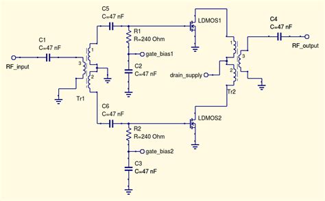
Circuit Diagram of a Push-Pull Amplifier
Here is a simplified circuit diagram of a push-pull amplifier:
                  +Vcc
                   |
                  +-+
                  | |
                  | |
                  | |
                  | |
                  +-+
                   |
                  +-+
                  | |
                  | |
                  | |
                  | |
                 |   |
        +-------+ Q1 +------+
        |        |   |      |
 Input -+        |   |      +- Output
        |        |   |      |
        +-------+ Q2 +------+
                 |   |
                  | |
                  | |
                  | |
                  | |
                  +-+
                   |
                  +-+
                  | |
                  | |
                  | |
                  | |
                  +-+
                   |
                  -Vcc
In this diagram, Q1 is the NPN transistor and Q2 is the PNP transistor. The input signal is split and fed into the bases of the two transistors, which amplify the signal and combine their outputs to produce the output signal.

Applications of Push-Pull Amplifiers
Push-pull amplifiers are used in a wide range of applications, including:
-
Audio amplifiers: Push-pull amplifiers are commonly used in audio amplifiers, such as those found in home stereo systems and musical instrument amplifiers.
-
Power amplifiers: Push-pull amplifiers are also used in power amplifiers, which are designed to drive large loads such as loudspeakers or motors.
-
RF amplifiers: Push-pull amplifiers can be used in radio frequency (RF) applications, such as in transmitters and receivers.
-
Servo amplifiers: Push-pull amplifiers are used in servo systems, which use feedback to control the position or speed of a motor or other actuator.

Designing a Push-Pull Amplifier
Designing a push-pull amplifier requires careful consideration of several factors, including:
-
Transistor selection: The transistors used in a push-pull amplifier must be carefully selected to ensure optimal performance. They should have high current gain, low distortion, and be closely matched in terms of their electrical characteristics.
-
Biasing: The transistors in a push-pull amplifier must be properly biased to ensure that they operate in their linear region and produce minimal distortion. This typically involves using a bias circuit to set the quiescent current through the transistors.
-
Output stage: The output stage of a push-pull amplifier must be carefully designed to ensure that it can deliver the required power to the load while maintaining low distortion and high efficiency. This may involve using heat sinks to dissipate excess heat, as well as using a transformer to match the impedance of the load to the output of the amplifier.
-
Feedback: Negative feedback can be used in a push-pull amplifier to reduce distortion and improve linearity. This involves taking a portion of the output signal and feeding it back into the input of the amplifier, which helps to cancel out any distortion products.
Troubleshooting Push-Pull Amplifiers
If a push-pull amplifier is not working properly, there are several things that can be checked:
-
Power supply: Make sure that the power supply is providing the correct voltage and current to the amplifier.
-
Transistors: Check the transistors for signs of damage or overheating. If a transistor is damaged, it will need to be replaced.
-
Bias circuit: Check the bias circuit to ensure that it is properly setting the quiescent current through the transistors.
-
Input signal: Make sure that the input signal is properly connected and has the correct amplitude and frequency.
-
Output stage: Check the output stage for signs of damage or overheating. If the output transformer or other components are damaged, they will need to be replaced.
Frequently Asked Questions (FAQ)
1. What is the difference between a push-pull amplifier and a single-ended amplifier?
A push-pull amplifier uses two complementary transistors to amplify both halves of the input signal, while a single-ended amplifier uses only one transistor to amplify one half of the input signal. Push-pull amplifiers are more efficient and produce less distortion than single-ended amplifiers, but are also more complex and expensive.
2. Can a push-pull amplifier be used for both audio and power applications?
Yes, push-pull amplifiers can be used for both audio and power applications. In audio applications, they are commonly used in home stereo systems and musical instrument amplifiers. In power applications, they are used to drive large loads such as loudspeakers or motors.
3. What is the purpose of the bias circuit in a push-pull amplifier?
The bias circuit in a push-pull amplifier is used to set the quiescent current through the transistors, which ensures that they operate in their linear region and produce minimal distortion. Without proper biasing, the transistors may not conduct for the entire input signal cycle, which can result in distortion and reduced efficiency.
4. How can negative feedback be used to improve the performance of a push-pull amplifier?
Negative feedback can be used in a push-pull amplifier to reduce distortion and improve linearity. This involves taking a portion of the output signal and feeding it back into the input of the amplifier, which helps to cancel out any distortion products. Negative feedback can also help to stabilize the gain of the amplifier and reduce its output impedance.
5. What should be done if a push-pull amplifier is producing distorted output?
If a push-pull amplifier is producing distorted output, there are several things that can be checked. First, make sure that the input signal is properly connected and has the correct amplitude and frequency. Next, check the bias circuit to ensure that it is properly setting the quiescent current through the transistors. Finally, check the output stage for signs of damage or overheating. If any of these components are not working properly, they will need to be repaired or replaced.
Conclusion
Push-pull amplifiers are an important type of electronic circuit that are used in a wide range of applications, from audio amplifiers to power amplifiers to servo systems. By using two complementary transistors to amplify both halves of the input signal, push-pull amplifiers are able to produce higher power output with lower distortion and higher efficiency than single-ended amplifiers.
Designing a push-pull amplifier requires careful consideration of several factors, including transistor selection, biasing, output stage design, and feedback. Proper design and troubleshooting can ensure that a push-pull amplifier operates at its best and produces the desired output.
As technology continues to advance, push-pull amplifiers will likely continue to play an important role in many electronic systems. By understanding the principles behind these amplifiers and how to design and troubleshoot them, engineers and technicians can ensure that they are able to meet the demands of a wide range of applications.
No responses yet