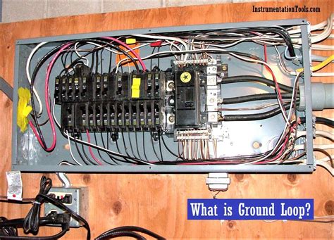
What is a Ground Loop?
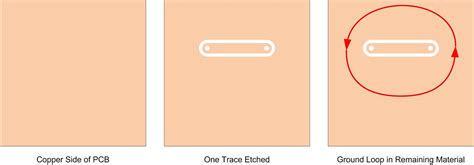
A ground loop is an unintentional current path between two or more points in an electrical system that are supposed to be at ground potential (0V). This can occur when there are multiple paths to ground and differences in potential between the ground points. Ground loops can cause issues like:
- Noise and interference in signals
- Erratic or unexpected behavior
- Damage to components from excessive currents
Ground loops are a common issue in PCB designs with multiple power supplies, mixed signal circuits (analog + digital), or connections to external equipment. Preventing ground loops requires careful PCB layout and system design.
Sources of Ground Loops
Ground loops can arise from several sources:
| Source | Description |
|---|---|
| Multiple ground paths | Current flows through unintended paths due to wiring errors, poor PCB layout, etc. |
| Shared ground impedance | Currents from different circuits interact due to resistance in shared ground connections |
| Earth ground connections | Potential differences between equipment connected to AC mains earth ground |
| Induced EMI | Currents induced by electromagnetic interference (EMI) from power lines, RF sources, etc. |
The key to preventing ground loops is to identify and eliminate these sources through proper PCB layout and system design practices.
PCB Layout Techniques
Use a Single Ground Plane
Using a single, continuous ground plane is one of the most effective ways to prevent ground loops on a PCB. A ground plane provides a low-impedance path for return currents and helps ensure that all ground points on the board are at the same potential.
Some guidelines for implementing a ground plane:
- Use a solid copper pour on one or more layers of the PCB
- Make the ground plane as large and continuous as possible
- Connect all ground points directly to the plane with vias
- Avoid splitting the ground plane or creating slots or cutouts
Separate Analog and Digital Grounds
In mixed-signal designs with both analog and digital circuits, it’s important to prevent noisy digital currents from interfering with sensitive analog signals. One way to do this is to use separate ground planes for the analog and digital sections of the board.
- Use a separate analog ground plane (AGND) for analog circuits
- Use a separate digital ground plane (DGND) for digital circuits
- Connect AGND and DGND at a single point, typically near the power supplies
- Route analog and digital signals on separate layers to minimize crosstalk
Use Star Grounding
Star grounding or single-point grounding is a technique where all ground connections are made to a single point, forming a star topology. This helps prevent ground loops by ensuring that there is only one path to ground for each circuit.
- Designate a single ground point on the PCB, typically near the power input
- Connect each circuit’s ground directly to the star ground point
- Keep ground traces as short as possible to minimize resistance and inductance
- Use a ground plane to provide a low-impedance path back to the star point

Cable and Connector Design
Ground loops often occur when connecting a PCB to external equipment or other systems. Proper cable and connector design is crucial to preventing these loops.
Use Shielded Cables
Shielded cables can help prevent ground loops by providing a low-impedance path for induced currents and rejecting electromagnetic interference (EMI).
- Use shielded cables for sensitive analog signals and high-speed digital interfaces
- Connect the shield to ground at one end of the cable, typically the source end
- Use 360° shielding (fully enclosed) for best performance
- Avoid pigtail or drain wire connections that can create high-impedance paths
Isolate Signals
In some cases, it may be necessary to electrically isolate signals to prevent ground loops between different systems. This can be done using isolation techniques such as:
- Optocouplers for digital signals
- Isolation amplifiers for analog signals
- Transformers for power and RF signals
Isolation breaks the galvanic connection between systems, preventing current from flowing through ground paths.
Use Differential Signaling
Differential signaling uses pairs of wires with opposite polarity to transmit signals. This makes the signal more immune to interference and reduces the impact of ground potential differences.
Common differential interfaces include:
- RS-485 for industrial control
- CAN bus for automotive systems
- Ethernet for networking
- USB for computer peripherals
When using differential signaling, it’s important to maintain the balance between the positive and negative lines and terminate them properly to prevent reflections.
System Design Considerations
Preventing ground loops requires a system-level approach that considers how different components and subsystems interact.
Use Separate Power Supplies
Using separate power supplies for different parts of the system can help isolate ground loops. For example:
- Use separate supplies for analog and digital circuits
- Use separate supplies for different boards or modules
- Use isolated supplies for equipment connected to AC mains
When using separate supplies, make sure to connect their grounds together at a single point to avoid creating additional ground loops.
Use Ground Fault Interrupters
Ground fault interrupters (GFIs) are devices that detect when current is flowing through an unintended path, such as a ground loop, and quickly disconnect power to prevent damage or safety hazards. GFIs are commonly used in:
- AC power distribution systems
- Wet or damp locations
- Outdoor equipment
- Medical devices
Using GFIs can help protect against ground loops and improve overall system safety.
Consider EMC Requirements
Meeting electromagnetic compatibility (EMC) requirements is important for preventing ground loops and ensuring reliable operation. Some key EMC considerations include:
- Conducted and radiated emissions
- Electrostatic discharge (ESD) immunity
- Transient and surge protection
- Cable shielding and filtering
Following industry standards and guidelines, such as FCC Part 15, CISPR 22, and IEC 61000, can help ensure EMC compliance and minimize the risk of ground loops.
FAQ
What is the difference between ground and earth?
Ground and earth are often used interchangeably, but they have slightly different meanings:
- Ground refers to a common reference point in an electrical system that is used as a zero-voltage potential.
- Earth refers specifically to the physical earth or soil that electrical systems may be connected to for safety or EMC reasons.
In most cases, ground and earth are connected together at some point, such as at the electrical service entrance for a building.
Can ground loops damage equipment?
Yes, ground loops can potentially damage equipment by causing excessive currents to flow through unintended paths. This can lead to overheating, component failure, or even fire in extreme cases.
Ground loops can also cause signal integrity issues, such as noise, distortion, or crosstalk, which can degrade performance or cause malfunctions.
How do I test for ground loops?
There are several ways to test for ground loops:
- Measure voltage between different ground points using a multimeter. Any voltage difference indicates a potential ground loop.
- Use an oscilloscope to look for noise or interference on signal lines that may be caused by ground loops.
- Disconnect cables or equipment one at a time to see if the issue goes away, indicating which connection may be causing the loop.
- Use a clamp-on current probe to measure current flowing through ground wires or shields. Current flow indicates a ground loop.
Can software help prevent ground loops?
While software itself cannot prevent ground loops, simulation and analysis tools can be used to identify potential issues during the PCB design process. For example:
- SPICE simulators can model ground impedances and help identify shared current paths.
- Power integrity tools can analyze voltage drops and current densities in ground planes.
- EMI simulators can predict coupling between signals and grounds.
Using these tools early in the design process can help identify and correct potential ground loop issues before the PCB is fabricated.
What if I can’t avoid a ground loop?
In some cases, it may not be possible to completely eliminate a ground loop due to system constraints or legacy designs. In these situations, there are still steps that can be taken to mitigate the impact:
- Use isolation techniques, such as optocouplers or transformers, to break the galvanic connection between systems.
- Add filtering, such as ferrite beads or capacitors, to reduce noise and interference on signal lines.
- Use shielding, such as shielded cables or enclosures, to minimize the coupling between circuits.
- Increase the impedance of the ground path, for example by using a resistor or inductor, to limit the current flow.
While these techniques may not eliminate the ground loop completely, they can help reduce its impact and improve overall system reliability.
Conclusion
Ground loops are a common issue in PCB designs that can cause noise, interference, and even damage to components. Preventing ground loops requires a combination of careful PCB layout, cable and connector design, and system-level considerations.
By following best practices such as using a single ground plane, separating analog and digital grounds, using star grounding, shielding cables, isolating signals, and using separate power supplies, designers can minimize the risk of ground loops and ensure reliable operation.
At the system level, using ground fault interrupters, meeting EMC requirements, and considering the interactions between different subsystems can further help prevent ground loops.
While it may not always be possible to completely eliminate ground loops, understanding their sources and using appropriate mitigation techniques can help minimize their impact and improve overall system performance.
No responses yet