Introduction to Power Supply Filtering
Power supply filtering is a crucial aspect of electronic circuit design that ensures the stability, reliability, and performance of electronic devices. In essence, power supply filtering involves the removal of unwanted noise, ripple, and other disturbances from the power supply signal, providing a clean and stable power source for the electronic components. This article explores the various power supply filtering options available, their working principles, advantages, and considerations for effective implementation.
The Importance of Power Supply Filtering
Electronic devices require a stable and clean power supply to function properly. However, power supply signals often contain unwanted noise, ripple, and other disturbances that can adversely affect the performance and reliability of electronic components. These disturbances can arise from various sources, such as:
- Power line noise
- Switching noise from power converters
- Electromagnetic interference (EMI)
- Ground loops
Power supply filtering helps mitigate these issues by attenuating the unwanted signal components and providing a smooth, stable power supply to the electronic circuit. Effective power supply filtering offers several benefits:
- Improved signal integrity
- Reduced electromagnetic interference (EMI)
- Enhanced circuit reliability
- Increased system stability
- Better overall performance
Types of Power Supply Filtering
There are several types of power supply filtering techniques, each with its own characteristics and suitability for different applications. The most common power supply filtering options include:
- Capacitive filtering
- Inductive filtering
- LC filtering
- Pi filtering
- Ferrite bead filtering
Capacitive Filtering
Capacitive filtering is one of the simplest and most widely used power supply filtering techniques. It involves placing a capacitor in parallel with the power supply and ground, creating a low-impedance path for high-frequency noise to bypass the load.
Working Principle
A capacitor acts as a short circuit for high-frequency signals and an open circuit for low-frequency signals. When placed in parallel with the power supply and ground, the capacitor provides a low-impedance path for high-frequency noise to flow through, effectively bypassing the load. This action filters out the high-frequency noise from the power supply signal, leaving a cleaner and more stable voltage for the electronic components.
Advantages
- Simple implementation
- Low cost
- Effective for high-frequency noise reduction
- Suitable for a wide range of applications
Considerations
- Capacitor selection (type, value, and voltage rating) is crucial for optimal performance
- Capacitor placement should be as close to the load as possible to minimize the effect of parasitic inductance
- Multiple capacitors with different values may be required to cover a wide frequency range
- Capacitors have limited effectiveness for low-frequency noise and ripple
Inductive Filtering
Inductive filtering employs an inductor in series with the power supply to attenuate high-frequency noise and ripple. This technique is particularly effective for reducing switching noise in power converters and other applications with high-current demands.
Working Principle
An inductor acts as a high-impedance element for high-frequency signals and a low-impedance element for low-frequency signals. When placed in series with the power supply, the inductor impedes the flow of high-frequency noise, effectively filtering it out from the power supply signal. The inductor also helps smooth out the current ripple, providing a more stable current to the load.
Advantages
- Effective for reducing switching noise and current ripple
- Suitable for high-current applications
- Can be used in conjunction with capacitive filtering for improved performance
Considerations
- Inductor selection (value, current rating, and core material) is crucial for optimal performance
- Inductors can be physically large and heavy, especially for high-current applications
- Inductors have limited effectiveness for high-frequency noise reduction
- Inductors can introduce additional series resistance, leading to voltage drop and power loss
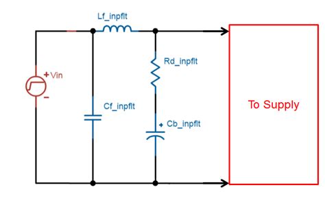
LC Filtering
LC filtering combines the benefits of capacitive and inductive filtering by using a series inductor and a parallel capacitor. This arrangement forms a low-pass filter that attenuates high-frequency noise while allowing low-frequency signals to pass through.
Working Principle
The series inductor impedes the flow of high-frequency noise, while the parallel capacitor provides a low-impedance path for the noise to bypass the load. Together, the inductor and capacitor form a low-pass filter with a specific cutoff frequency, determined by the values of the inductor and capacitor. Frequencies above the cutoff frequency are attenuated, while frequencies below the cutoff frequency are allowed to pass through with minimal attenuation.
Advantages
- Effective for reducing both high-frequency noise and current ripple
- Provides a sharper roll-off compared to capacitive or inductive filtering alone
- Suitable for a wide range of applications
Considerations
- Proper selection of inductor and capacitor values is essential for achieving the desired cutoff frequency and attenuation
- The inductor and capacitor values should be chosen to minimize the impact of component parasitics
- LC filters can resonate at their natural frequency, potentially leading to instability if not properly damped
- The physical size of the inductor and capacitor can be a constraint in space-limited applications
Pi Filtering
Pi filtering is an advanced form of LC filtering that uses two parallel capacitors and one series inductor, resembling the Greek letter π. This configuration provides improved high-frequency noise attenuation and a sharper roll-off compared to a single-stage LC filter.
Working Principle
The series inductor impedes the flow of high-frequency noise, while the two parallel capacitors provide low-impedance paths for the noise to bypass the load. The first capacitor acts as a pre-filter, reducing the high-frequency noise before it reaches the inductor. The second capacitor acts as a post-filter, further attenuating any remaining high-frequency noise after the inductor. The overall result is a more effective low-pass filter with a sharper roll-off and better high-frequency noise attenuation.
Advantages
- Excellent high-frequency noise attenuation
- Sharper roll-off compared to single-stage LC filters
- Provides additional attenuation for EMI and other high-frequency disturbances
Considerations
- Proper selection of inductor and capacitor values is crucial for achieving the desired performance
- The additional components increase the filter’s complexity and cost
- The physical size of the filter can be larger compared to single-stage LC filters
- Proper grounding and layout techniques are essential to minimize the impact of parasitics
Ferrite Bead Filtering
Ferrite bead filtering is a specialized technique that utilizes the frequency-dependent impedance characteristics of ferrite materials to suppress high-frequency noise. Ferrite beads are small, cylindrical components that contain a ferrite core material with high magnetic permeability.
Working Principle
Ferrite beads act as frequency-dependent resistors, presenting a high impedance to high-frequency signals while allowing low-frequency signals to pass through with minimal attenuation. When placed in series with the power supply, the ferrite bead impedes the flow of high-frequency noise, effectively filtering it out from the power supply signal. The impedance of the ferrite bead increases with frequency, making it particularly effective for suppressing high-frequency noise and EMI.
Advantages
- Compact size and lightweight
- Effective for suppressing high-frequency noise and EMI
- Low DC resistance, minimizing voltage drop and power loss
- Suitable for space-constrained applications
Considerations
- Ferrite bead selection (material, impedance, and current rating) is crucial for optimal performance
- Ferrite beads have limited effectiveness for low-frequency noise and ripple
- The impedance of ferrite beads is dependent on the current flowing through them, which can affect their performance
- Ferrite beads can saturate in the presence of high DC currents, reducing their effectiveness
Implementing Power Supply Filtering
Effective power supply filtering requires careful consideration of several factors, including:
- Identifying the dominant noise sources and their frequency ranges
- Selecting the appropriate filtering technique(s) based on the noise characteristics and application requirements
- Choosing the proper component values and ratings for optimal performance
- Minimizing the impact of component parasitics through proper layout and grounding techniques
- Validating the filter performance through simulation and measurement
Identifying Noise Sources
The first step in implementing effective power supply filtering is to identify the dominant noise sources and their frequency ranges. Common noise sources include:
- Power line noise (50/60 Hz and harmonics)
- Switching noise from power converters (typically in the kHz to MHz range)
- Electromagnetic interference (EMI) from nearby electronic devices or external sources
- Ground loops and other system-level noise sources
By understanding the characteristics of the noise sources, designers can select the most appropriate filtering techniques and component values to mitigate their effects.
Selecting the Appropriate Filtering Technique(s)
The choice of filtering technique(s) depends on several factors, including:
- The frequency range and amplitude of the noise sources
- The desired level of attenuation and roll-off characteristics
- The available board space and component footprint
- The cost and complexity of the implementation
In many cases, a combination of filtering techniques may be necessary to achieve the desired performance. For example, a pi filter can be used in conjunction with ferrite beads to provide a comprehensive solution for high-frequency noise and EMI suppression.
Choosing Proper Component Values and Ratings
The selection of component values and ratings is critical for achieving optimal filter performance. Key considerations include:
- Capacitor type (ceramic, tantalum, electrolytic) and dielectric material
- Capacitor value and voltage rating
- Inductor value, current rating, and core material
- Ferrite bead impedance and current rating
Designers should also consider the impact of component parasitics, such as equivalent series resistance (ESR) and equivalent series inductance (ESL), which can affect the filter’s performance at high frequencies.
Minimizing the Impact of Parasitics
Proper layout and grounding techniques are essential for minimizing the impact of component parasitics and ensuring the filter’s effectiveness. Some best practices include:
- Placing the filter components as close to the load as possible to minimize the effect of trace inductance
- Using wide, low-impedance traces for power supply and ground connections
- Implementing a solid ground plane to provide a low-impedance return path for high-frequency currents
- Minimizing the loop area of power supply and ground traces to reduce the effect of magnetic coupling
Validating Filter Performance
Validating the filter performance through simulation and measurement is crucial for ensuring that the design meets the specified requirements. Simulation tools, such as SPICE or electromagnetic field solvers, can help predict the filter’s frequency response and attenuation characteristics. Measurement techniques, such as frequency response analysis and spectrum analysis, can be used to verify the filter’s performance in the actual hardware.

Frequently Asked Questions (FAQ)
- What is the difference between capacitive and inductive filtering?
-
Capacitive filtering uses a capacitor in parallel with the power supply and ground to provide a low-impedance path for high-frequency noise, while inductive filtering uses an inductor in series with the power supply to impede the flow of high-frequency noise and smooth out current ripple.
-
Can I use a single capacitor for power supply filtering?
-
While a single capacitor can provide some level of high-frequency noise reduction, it may not be sufficient for optimal performance. Using multiple capacitors with different values and placing them close to the load is often necessary to cover a wide frequency range and minimize the effect of parasitic inductance.
-
How do I select the proper inductor value for my power supply filter?
-
The inductor value should be chosen based on the desired cutoff frequency, current rating, and acceptable voltage drop. A higher inductance value will provide better low-frequency noise attenuation but may result in a larger voltage drop and physical size. It is essential to consider the trade-offs and select a value that meets the specific requirements of the application.
-
What is the advantage of using a pi filter over a single-stage LC filter?
-
A pi filter provides improved high-frequency noise attenuation and a sharper roll-off compared to a single-stage LC filter. The additional parallel capacitor in a pi filter helps to pre-filter the high-frequency noise before it reaches the inductor, resulting in better overall noise suppression.
-
Can I use ferrite beads in combination with other filtering techniques?
- Yes, ferrite beads can be used in combination with other filtering techniques, such as capacitive or LC filtering, to provide a comprehensive solution for power supply noise reduction. Ferrite beads are particularly effective for suppressing high-frequency noise and EMI, while capacitive and LC filters can help attenuate lower-frequency noise and ripple.
Conclusion
Power supply filtering is a critical aspect of electronic circuit design, ensuring the stability, reliability, and performance of electronic devices. By understanding the various filtering techniques available, their working principles, and the considerations for effective implementation, designers can select the most appropriate solution for their specific application.
Capacitive, inductive, LC, pi, and ferrite bead filtering are among the most common power supply filtering options, each with its own strengths and limitations. Effective power supply filtering requires careful consideration of noise sources, component selection, layout, and validation through simulation and measurement.
By implementing the appropriate power supply filtering techniques and following best practices for component selection and layout, designers can achieve a clean, stable power supply for their electronic circuits, leading to improved signal integrity, reduced EMI, and enhanced overall system performance.
No responses yet