Introduction to Pi Filter Design
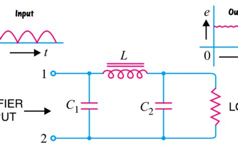
Pi filters are a type of passive electronic filter that is commonly used in power supply designs to reduce noise and improve power quality. The name “pi” comes from the resemblance of the filter’s schematic diagram to the Greek letter π (pi). Pi filters consist of two capacitors and an inductor arranged in a pi configuration, which provides effective filtering of both differential mode and common mode noise.
In power supply applications, pi filters are often employed at the input stage to attenuate high-frequency noise from the AC mains or other power sources. They can also be used at the output stage to smooth out ripple and spikes in the DC voltage, ensuring a clean and stable power supply to the load.
Key Components of a Pi Filter
A typical pi filter comprises the following components:
-
Input Capacitor (C1): This capacitor is connected in parallel with the input voltage source and helps to shunt high-frequency noise to ground.
-
Inductor (L): The inductor is connected in series between the input and output capacitors. It acts as a low-pass filter, attenuating high-frequency noise while allowing the desired DC or low-frequency signal to pass through.
-
Output Capacitor (C2): This capacitor is connected in parallel with the load and further filters out any remaining high-frequency noise, providing a smooth output voltage.
The values of the capacitors and inductor are carefully chosen based on the desired cutoff frequency, which determines the range of frequencies that the filter will attenuate.
Designing a Pi Filter for Power Supplies
Step 1: Determine the Filter Requirements
Before designing a pi filter, it is essential to understand the specific requirements of the power supply application. This includes factors such as:
- Input voltage range
- Output voltage and current requirements
- Expected load variations
- Noise and ripple specifications
- Space constraints and component availability
These requirements will guide the selection of appropriate component values and help optimize the filter’s performance.
Step 2: Calculate the Cutoff Frequency
The cutoff frequency (fc) is a critical parameter in pi filter design. It represents the frequency at which the filter’s attenuation begins to take effect. The choice of cutoff frequency depends on the frequency range of the noise to be filtered out and the desired signal bandwidth.
To calculate the cutoff frequency, use the following formula:
fc = 1 / (2π√(LC))
Where:
– fc is the cutoff frequency in hertz (Hz)
– L is the inductance in henries (H)
– C is the capacitance in farads (F)
For power supply applications, the cutoff frequency is typically chosen to be at least one decade below the switching frequency of the power converter to ensure effective noise attenuation.
Step 3: Select the Inductor Value
The inductor value is a critical component in determining the filter’s performance. A larger inductor value provides better noise attenuation but also increases the filter’s size and cost. The inductor value can be calculated using the following formula:
L = (Vripple × Dmax) / (Iripple × fs)
Where:
– L is the inductance in henries (H)
– Vripple is the maximum allowable output voltage ripple in volts (V)
– Dmax is the maximum duty cycle of the power converter
– Iripple is the maximum allowable inductor current ripple in amperes (A)
– fs is the switching frequency of the power converter in hertz (Hz)
It is important to choose an inductor with a current rating higher than the expected maximum load current to prevent saturation and ensure proper operation.
Step 4: Choose the Capacitor Values
The input and output capacitors in a pi filter serve to bypass high-frequency noise and smooth out voltage ripple. The capacitor values are selected based on the desired ripple attenuation and the filter’s cutoff frequency.
For the input capacitor (C1), a larger value provides better high-frequency noise attenuation. However, the capacitor’s voltage rating must be sufficient to withstand the input voltage range, including any transient spikes.
The output capacitor (C2) is chosen to achieve the desired output voltage ripple. The capacitor value can be calculated using the following formula:
C2 = (Iripple) / (8 × fs × Vripple)
Where:
– C2 is the output capacitance in farads (F)
– Iripple is the maximum allowable inductor current ripple in amperes (A)
– fs is the switching frequency of the power converter in hertz (Hz)
– Vripple is the maximum allowable output voltage ripple in volts (V)
It is recommended to use capacitors with low equivalent series resistance (ESR) to minimize power losses and improve filter efficiency.
Step 5: Verify the Filter’s Performance
Once the component values have been selected, it is essential to verify the filter’s performance through simulation and practical testing. Simulation tools like SPICE can be used to analyze the filter’s frequency response, attenuation characteristics, and transient behavior.
Practical testing should be conducted under various load conditions to ensure that the filter meets the desired specifications. Oscilloscope measurements can be used to examine the input and output waveforms, measure the ripple and noise levels, and validate the filter’s effectiveness.
Pi Filter Design Considerations
When designing pi filters for power supplies, several key considerations should be taken into account to ensure optimal performance and reliability:
Component Selection
The choice of components plays a crucial role in the filter’s performance and longevity. Capacitors should have low ESR and be rated for the expected voltage and temperature range. Inductors should have low DC resistance and be designed to handle the required current without saturation.
Surface-mount components are often preferred for their compact size and low parasitic inductance. However, through-hole components may be used in high-power applications or when greater heat dissipation is required.
PCB Layout
Proper PCB layout is essential for the effective operation of pi filters. The filter components should be placed as close to the power input and output as possible to minimize the loop area and reduce the impact of parasitic inductance.
The use of ground planes and proper grounding techniques can help to minimize noise coupling and improve the filter’s performance. It is also important to consider the current paths and ensure adequate trace widths to handle the expected currents without excessive voltage drop or heating.
EMI Considerations
Pi filters are often used to mitigate electromagnetic interference (EMI) in power supply designs. However, the filter itself can also be a source of EMI if not properly designed and implemented.
To minimize EMI, it is essential to use shielded inductors or inductors with closed magnetic paths. The filter components should be physically separated from sensitive analog or digital circuits to prevent coupling of noise.
Additionally, the use of common-mode chokes or Y-capacitors can be considered to further suppress common-mode noise and meet EMI regulatory requirements.
Thermal Management
Power supply filters dissipate heat due to the losses in the inductor and capacitors. Proper thermal management is necessary to ensure the filter components operate within their rated temperature range and to prevent premature failure.
The use of heat sinks, thermal pads, or thermal vias can help to dissipate heat from the filter components to the PCB or chassis. In high-power applications, forced air cooling or liquid cooling may be necessary to maintain acceptable operating temperatures.
Testing and Validation
Thorough testing and validation are critical to ensure the pi filter meets the desired performance specifications and reliability requirements. This includes both bench testing and environmental testing.
Bench testing should involve measuring the filter’s frequency response, attenuation characteristics, and transient response under various load conditions. Environmental testing, such as temperature cycling and vibration testing, helps to assess the filter’s robustness and long-term reliability.

Real-World Applications of Pi Filters in Power Supplies
Pi filters find widespread use in various power supply applications across different industries. Some common examples include:
Switched-Mode Power Supplies (SMPS)
Switched-mode power supplies, such as buck converters and boost converters, often employ pi filters at the input and output stages. The input pi filter helps to attenuate high-frequency noise from the power source, while the output pi filter reduces ripple and improves the quality of the regulated DC voltage.
Uninterruptible Power Supplies (UPS)
Uninterruptible power supplies rely on pi filters to provide clean and stable power to critical loads during mains power disruptions. The pi filter at the input stage helps to filter out noise and transients from the AC mains, ensuring a clean input to the UPS inverter. The output pi filter smooths out the inverter’s output voltage, providing a clean and regulated power supply to the connected equipment.
Audio and Video Equipment
High-quality audio and video equipment often incorporate pi filters in their power supply designs to minimize noise and interference. The pi filters help to attenuate high-frequency noise from the mains power, preventing it from contaminating the sensitive analog and digital circuits. This results in improved signal-to-noise ratio, reduced distortion, and better overall audio and video quality.
Industrial Control Systems
Industrial control systems, such as programmable logic controllers (PLCs) and distributed control systems (DCS), rely on robust and reliable power supplies. Pi filters are commonly used in these power supplies to attenuate noise and ensure stable operation in harsh industrial environments. The filters help to protect the control electronics from power line disturbances, ensuring reliable and uninterrupted operation.

Conclusion
Pi filters are an essential component in power supply designs, providing effective attenuation of high-frequency noise and improving power quality. By carefully selecting the filter components and considering factors such as cutoff frequency, inductor and capacitor values, and PCB layout, designers can optimize the performance of pi filters to meet the specific requirements of their power supply applications.
Proper testing and validation are crucial to ensure the pi filter meets the desired specifications and reliability standards. By incorporating pi filters in power supply designs, engineers can achieve cleaner, more stable, and reliable power delivery, ultimately enhancing the performance and longevity of electronic systems.
Frequently Asked Questions (FAQ)
1. What is the purpose of a pi filter in a power supply?
A pi filter in a power supply serves to attenuate high-frequency noise and improve power quality. It helps to reduce ripple, spikes, and electromagnetic interference (EMI) from the power source, ensuring a clean and stable power supply to the load.
2. How do I select the appropriate cutoff frequency for a pi filter?
The cutoff frequency of a pi filter is typically chosen to be at least one decade below the switching frequency of the power converter. This ensures effective attenuation of the high-frequency noise while allowing the desired signal to pass through. The exact choice of cutoff frequency depends on the specific noise spectrum and the desired signal bandwidth.
3. Can pi filters be used in both AC and DC power supplies?
Yes, pi filters can be used in both AC and DC power supplies. In AC power supplies, pi filters are commonly used at the input stage to attenuate high-frequency noise from the mains power. In DC power supplies, pi filters are used at both the input and output stages to reduce ripple and improve the quality of the regulated DC voltage.
4. What are the advantages of using surface-mount components in pi filters?
Surface-mount components offer several advantages in pi filter designs. They have smaller footprints, allowing for more compact filter layouts. Surface-mount components also have lower parasitic inductance compared to through-hole components, which helps to improve high-frequency performance and reduce noise coupling.
5. How can I ensure proper thermal management of pi filter components?
To ensure proper thermal management of pi filter components, several techniques can be employed. These include the use of heat sinks, thermal pads, or thermal vias to dissipate heat from the components to the PCB or chassis. In high-power applications, forced air cooling or liquid cooling may be necessary to maintain acceptable operating temperatures. Proper component selection and derating also play a crucial role in thermal management.
No responses yet