Introduction to PFC Circuits
Power Factor Correction (PFC) circuits are essential components in modern power systems, ensuring efficient power delivery and compliance with international standards. PFC circuits improve the power factor of a system by minimizing the phase difference between voltage and current waveforms, reducing harmonic distortion, and optimizing power utilization. This article delves into the design and layout considerations for PFC circuits in power systems, covering key aspects such as topology selection, component choice, layout techniques, and frequently asked questions.
Understanding Power Factor and Harmonic Distortion
Before diving into PFC circuit design, it is crucial to understand the concepts of power factor and harmonic distortion. Power factor is the ratio of real power to apparent power in an electrical system. A power factor of 1 indicates that all the power supplied is being effectively utilized, while a lower power factor suggests inefficiencies and wasted energy. Harmonic distortion, on the other hand, refers to the presence of higher-frequency components in the current waveform, which can cause power quality issues and overheating of components.
Power Factor Correction Techniques
There are two primary techniques for achieving power factor correction: passive PFC and active PFC.
Passive PFC
Passive PFC employs passive components such as capacitors and inductors to filter out harmonic distortion and improve power factor. While simple and cost-effective, passive PFC has limitations in terms of achievable power factor and may require bulky components for high-power applications.
Active PFC
Active PFC utilizes power electronic switches, such as MOSFETs or IGBTs, along with control circuitry to shape the input current waveform and achieve near-unity power factor. Active PFC offers superior performance compared to passive PFC, with the ability to achieve power factors close to 1 and reduced harmonic distortion.
PFC Circuit Topologies
Several PFC circuit topologies are commonly used in power systems, each with its own advantages and trade-offs. The choice of topology depends on factors such as power level, efficiency requirements, and cost constraints.
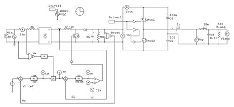
Boost PFC
The boost PFC topology is widely adopted due to its simplicity and effectiveness. It employs a boost converter to shape the input current and regulate the output voltage. The boost PFC circuit operates in continuous conduction mode (CCM) or discontinuous conduction mode (DCM), depending on the inductor current.
Interleaved PFC
Interleaved PFC utilizes multiple boost converters connected in parallel, with their switching actions phase-shifted to reduce input current ripple and improve efficiency. This topology is suitable for high-power applications and offers benefits such as reduced component stress and improved thermal management.
Bridgeless PFC
Bridgeless PFC topologies eliminate the need for a full-bridge rectifier at the input stage, reducing conduction losses and improving efficiency. Examples of bridgeless PFC topologies include the totem-pole PFC and the dual-boost PFC.

Component Selection for PFC Circuits
Proper component selection is crucial for optimal PFC circuit performance and reliability. Key components in a PFC circuit include:
Power Semiconductors
MOSFETs or IGBTs are commonly used as the main switching devices in PFC circuits. The choice between MOSFETs and IGBTs depends on the power level and switching frequency requirements. MOSFETs are preferred for lower power levels and higher switching frequencies, while IGBTs are suitable for high-power applications.
Inductors
The inductor is a critical component in PFC circuits, as it stores energy and shapes the input current waveform. The inductor value is determined based on the desired current ripple, switching frequency, and power level. High-quality magnetic cores, such as ferrite or powder cores, are used to minimize losses and ensure stable operation.
Capacitors
Capacitors are used for energy storage and filtering in PFC circuits. The output capacitor is sized to maintain a stable output voltage and minimize voltage ripple. Low-ESR (Equivalent Series Resistance) capacitors, such as ceramic or film capacitors, are preferred to reduce losses and improve transient response.
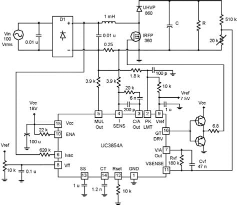
Control ICs
PFC control ICs simplify the design process by integrating various control and protection functions. These ICs typically include features such as current sensing, voltage regulation, over-current protection, and soft-start functionality. Popular PFC control ICs include the UCC28180 from Texas Instruments and the FAN9611 from ON Semiconductor.
PFC Circuit Layout Considerations
Proper layout techniques are essential for optimal PFC circuit performance, minimizing electromagnetic interference (EMI), and ensuring reliable operation. Key layout considerations include:
Component Placement
Strategic component placement is crucial for minimizing parasitic inductances and capacitances, which can impact circuit performance. Power components, such as MOSFETs and inductors, should be placed close to each other to reduce loop areas and minimize stray inductances. Control circuitry should be separated from power paths to avoid noise coupling.
Grounding and Shielding
Proper grounding and shielding techniques are essential for minimizing EMI and ensuring stable operation. A solid ground plane should be used to provide a low-impedance return path for high-frequency currents. Sensitive control circuitry should be shielded from high-frequency noise using ground planes or shield cans.
Thermal Management
PFC circuits generate heat due to power losses in components such as MOSFETs and inductors. Adequate thermal management is necessary to ensure reliable operation and prevent component damage. Heatsinks, thermal vias, and proper airflow design should be considered to dissipate heat effectively.
EMI Mitigation
PFC circuits can be a source of EMI due to high-frequency switching. Proper layout techniques and EMI mitigation measures are essential to comply with electromagnetic compatibility (EMC) standards. Common EMI mitigation techniques include the use of snubber circuits, input filters, and shielded cables.
Frequently Asked Questions (FAQ)
1. What is the purpose of a PFC circuit in power systems?
A: The purpose of a PFC circuit in power systems is to improve the power factor by minimizing the phase difference between voltage and current waveforms, reducing harmonic distortion, and optimizing power utilization. PFC circuits ensure efficient power delivery and compliance with international standards.
2. What are the advantages of active PFC over passive PFC?
A: Active PFC offers several advantages over passive PFC, including the ability to achieve near-unity power factor, reduced harmonic distortion, and improved efficiency. Active PFC circuits can also operate over a wide range of input voltages and are suitable for high-power applications.
3. How does the choice of PFC circuit topology affect performance?
A: The choice of PFC circuit topology affects performance in terms of efficiency, power density, and component stress. For example, the boost PFC topology is simple and effective but may have limitations in terms of efficiency at light loads. Interleaved PFC offers improved efficiency and reduced input current ripple, while bridgeless PFC topologies reduce conduction losses.
4. What are the key component selection considerations for PFC circuits?
A: Key component selection considerations for PFC circuits include the choice of power semiconductors (MOSFETs or IGBTs), inductor value and core material, capacitor type and ESR, and control ICs. The selection depends on factors such as power level, switching frequency, efficiency requirements, and cost constraints.
5. How can EMI be mitigated in PFC circuits?
A: EMI in PFC circuits can be mitigated through proper layout techniques and the use of EMI mitigation measures. These include strategic component placement, solid grounding and shielding, the use of snubber circuits, input filters, and shielded cables. Compliance with EMC standards is essential to ensure reliable operation and minimize interference with other electronic devices.
Conclusion
PFC circuit design and layout are critical aspects of power system design, ensuring efficient power delivery, improved power quality, and compliance with international standards. Understanding the concepts of power factor and harmonic distortion, selecting appropriate PFC topologies and components, and implementing proper layout techniques are essential for optimal PFC circuit performance.
By considering factors such as topology selection, component choice, layout considerations, and EMI mitigation, designers can develop robust and efficient PFC circuits for various power system applications. Proper PFC circuit design not only enhances power utilization but also contributes to energy conservation and reduces the overall cost of ownership in power systems.
As power quality standards continue to evolve and the demand for efficient power systems grows, PFC circuits will remain an integral part of modern power electronics. By staying updated with the latest advancements in PFC circuit design and layout techniques, designers can develop innovative solutions that meet the ever-increasing demands of power systems while ensuring reliability, efficiency, and compliance with industry standards.
| Parameter | Boost PFC | Interleaved PFC | Bridgeless PFC |
|---|---|---|---|
| Efficiency | Moderate | High | High |
| Power Density | Moderate | High | High |
| Component Count | Low | Moderate | Low to Moderate |
| Input Current Ripple | Moderate | Low | Low to Moderate |
| Conduction Losses | Moderate | Low | Low |
| Suitability for High Power | Moderate | High | High |
Table 1: Comparison of PFC Circuit Topologies
By understanding the characteristics and trade-offs of different PFC circuit topologies, as summarized in Table 1, designers can make informed decisions based on the specific requirements of their power system applications. Whether it’s the simplicity and cost-effectiveness of the boost PFC, the improved efficiency and reduced ripple of interleaved PFC, or the reduced conduction losses of bridgeless PFC, each topology has its own merits and suitability for different power levels and efficiency targets.
In conclusion, PFC circuit design and layout play a vital role in ensuring the efficiency, reliability, and compliance of power systems. By carefully considering the various aspects discussed in this article, including topology selection, component choice, layout techniques, and EMI mitigation, designers can develop optimized PFC circuits that meet the demanding requirements of modern power applications. As power electronics continue to advance, staying updated with the latest trends and techniques in PFC circuit design will be crucial for engineers and researchers in the field.
No responses yet