What is a Peak Detector?
A peak detector, also known as a peak hold circuit, is an electronic circuit that captures and holds the maximum value of an input signal. It tracks the peak amplitude of the signal and stores it until the circuit is reset or a higher peak is detected. Peak detectors are useful for measuring the highest value of a signal over a period of time, even if the signal is rapidly changing or has a short duration.
Key Characteristics of a Peak Detector
- Capture and Hold: A peak detector captures the maximum value of an input signal and holds it until the circuit is reset or a higher peak is detected.
- Fast Response: Peak detectors should have a fast response time to accurately capture the peak value of the signal.
- Minimal Droop: The held peak value should have minimal droop over time to ensure accurate measurement.
- Adjustable Decay: Some peak detectors allow for adjustable decay time, which determines how long the peak value is held before it starts to decrease.
Basic Peak Detector Circuit
The most basic peak detector circuit consists of a diode, a capacitor, and a resistor. Let’s examine the role of each component and how they work together to form a peak detector.
Circuit Components
- Diode: The diode acts as a one-way valve, allowing current to flow in only one direction. When the input signal is higher than the voltage across the capacitor, the diode conducts and charges the capacitor to the peak value of the signal.
- Capacitor: The capacitor stores the peak value of the input signal. It is charged through the diode when the input signal reaches its peak and holds the voltage even after the signal starts to decrease.
- Resistor: The resistor provides a discharge path for the capacitor. It determines the decay time of the peak detector, which is the time taken for the held peak value to decrease to a certain level.
Circuit Diagram
| Component | Value |
|---|---|
| Diode | 1N4148 |
| Capacitor | 1 μF |
| Resistor | 1 MΩ |
How it Works
- When the input signal is higher than the voltage across the capacitor, the diode conducts and charges the capacitor to the peak value of the signal.
- Once the input signal starts to decrease, the diode becomes reverse-biased, and the capacitor holds the peak voltage.
- The resistor slowly discharges the capacitor, causing the held peak value to decrease over time. The discharge time is determined by the RC time constant, which is the product of the resistor value and the capacitor value.

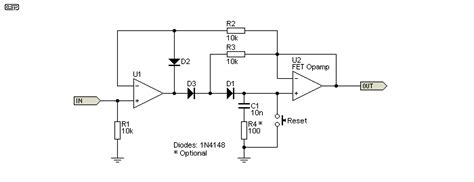
Precision Peak Detector Circuit
While the basic peak detector circuit is simple and easy to understand, it has some limitations. The forward voltage drop of the diode introduces an error in the peak detection, and the discharge time is fixed by the RC time constant. A precision peak detector circuit addresses these issues by using an operational amplifier (op-amp) to buffer the input signal and provide a high-impedance discharge path.
Circuit Components
- Op-Amp: The op-amp serves as a buffer, isolating the input signal from the peak detector circuit. It also provides a high-impedance discharge path for the capacitor.
- Diode: The diode allows the capacitor to charge when the input signal is higher than the voltage across the capacitor.
- Capacitor: The capacitor stores the peak value of the input signal.
- Resistor: The resistor determines the discharge time of the peak detector. A higher resistor value results in a longer discharge time.
Circuit Diagram
| Component | Value |
|---|---|
| Op-Amp | LM358 |
| Diode | 1N4148 |
| Capacitor | 1 μF |
| Resistor | 10 MΩ |
How it Works
- The op-amp buffers the input signal and provides a high-impedance input to the peak detector circuit.
- When the input signal is higher than the voltage across the capacitor, the diode conducts and charges the capacitor to the peak value of the signal.
- Once the input signal starts to decrease, the diode becomes reverse-biased, and the capacitor holds the peak voltage.
- The resistor connected between the op-amp output and the capacitor provides a high-impedance discharge path. The discharge time is determined by the resistor value and the capacitor value.

Peak Detector with Adjustable Decay
In some applications, it may be desirable to have control over the decay time of the peak detector. This can be achieved by replacing the fixed resistor in the precision peak detector circuit with a potentiometer.
Circuit Components
- Op-Amp: The op-amp serves as a buffer and provides a high-impedance discharge path.
- Diode: The diode allows the capacitor to charge when the input signal is higher than the voltage across the capacitor.
- Capacitor: The capacitor stores the peak value of the input signal.
- Potentiometer: The potentiometer allows for adjustable decay time. By changing the resistance value, the discharge time of the peak detector can be controlled.
Circuit Diagram
| Component | Value |
|---|---|
| Op-Amp | LM358 |
| Diode | 1N4148 |
| Capacitor | 1 μF |
| Potentiometer | 1 MΩ |
How it Works
- The op-amp buffers the input signal and provides a high-impedance input to the peak detector circuit.
- When the input signal is higher than the voltage across the capacitor, the diode conducts and charges the capacitor to the peak value of the signal.
- Once the input signal starts to decrease, the diode becomes reverse-biased, and the capacitor holds the peak voltage.
- The potentiometer connected between the op-amp output and the capacitor provides an adjustable discharge path. By changing the resistance value of the potentiometer, the discharge time can be controlled.

Applications of Peak Detectors
Peak detectors find applications in various fields, including:
- Audio Processing: Peak detectors are used in audio compressors, limiters, and automatic gain control (AGC) circuits to detect and control the peak levels of audio signals.
- Instrumentation: Peak detectors are used in measurement and instrumentation systems to capture and hold the maximum value of a signal for analysis or display.
- Control Systems: Peak detectors are used in control systems to detect and respond to peak levels of signals, such as in overvoltage protection circuits or peak current limiters.
- Signal Conditioning: Peak detectors are used in signal conditioning circuits to remove noise and extract the peak values of signals for further processing.
Frequently Asked Questions (FAQ)
-
What is the difference between a peak detector and a sample-and-hold circuit?
A peak detector captures and holds the maximum value of a signal, while a sample-and-hold circuit captures and holds the instantaneous value of a signal at a specific point in time. -
Can a peak detector detect negative peaks?
A standard peak detector circuit detects positive peaks. To detect negative peaks, the diode in the circuit needs to be reversed, and the op-amp should be configured as an inverting amplifier. -
How does the capacitor value affect the performance of a peak detector?
The capacitor value determines the hold time and the response time of the peak detector. A larger capacitor value will result in a longer hold time but a slower response time, while a smaller capacitor value will have a faster response time but a shorter hold time. -
What is the purpose of the op-amp in a precision peak detector circuit?
The op-amp in a precision peak detector circuit serves two purposes: it buffers the input signal, isolating it from the peak detector circuit, and it provides a high-impedance discharge path for the capacitor, allowing for accurate peak detection and adjustable decay time. -
Can a peak detector be used for AC signals?
Yes, a peak detector can be used for AC signals. However, the circuit needs to be modified to include a rectifier stage before the peak detector to convert the AC signal into a pulsating DC signal. The rectifier can be a half-wave rectifier or a full-wave rectifier, depending on the application requirements.
Conclusion
Peak detector circuits are essential tools in many electronic applications, allowing for the capture and measurement of the maximum value of a signal. By understanding the basic principles and components of peak detectors, you can build your own circuits using simple components like diodes, capacitors, and resistors.
This comprehensive guide has covered the fundamentals of peak detectors, including the basic peak detector circuit, the precision peak detector circuit, and the peak detector with adjustable decay. We have also explored the applications of peak detectors in various fields and answered frequently asked questions.
With this knowledge, you can now confidently design and build peak detector circuits for your own projects and experiments. Remember to choose the appropriate components and values based on your specific requirements, and always test your circuits thoroughly to ensure proper functionality.
Happy peak detecting!
No responses yet