Introduction to PCBA Drawing Requirements
Printed Circuit Board Assembly (PCBA) is a crucial process in the manufacturing of electronic devices. It involves the assembly of various electronic components onto a printed circuit board (PCB) to create a functional electronic system. To ensure the accuracy and efficiency of the PCBA process, it is essential to have a well-defined set of requirements for the assembly drawing.
In this article, we will explore the basic requirements for PCBA drawing, including the essential elements that should be included, the format and layout of the drawing, and the best practices for creating an effective assembly drawing.
The Importance of PCBA Drawing
Before we dive into the specific requirements for PCBA drawing, let’s first understand why it is so important. A PCBA drawing serves as a visual guide for the assembly process, providing clear instructions on how to place and orient each component on the PCB. It also helps to ensure that the final product meets the desired specifications and functions as intended.
Without a well-defined PCBA drawing, the assembly process can be prone to errors and inconsistencies, leading to costly rework and delays. A clear and accurate drawing can help to streamline the assembly process, reduce the risk of errors, and ultimately lead to a higher quality final product.

Essential Elements of a PCBA Drawing
A PCBA drawing should include several essential elements to provide a clear and comprehensive guide for the assembly process. These elements include:
Bill of Materials (BOM)
The BOM is a list of all the components that are required for the assembly of the PCB. It should include the part number, description, quantity, and any other relevant information for each component. The BOM should be clearly labeled and easy to reference during the assembly process.
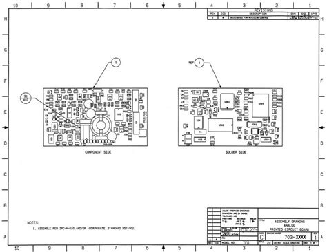
Component Placement Diagram
The component placement diagram is a visual representation of where each component should be placed on the PCB. It should show the exact location and orientation of each component, as well as any special instructions for placement (e.g. polarity, orientation, etc.).
Assembly Notes
Assembly notes provide additional information and instructions for the assembly process. This can include things like special handling requirements, testing procedures, or any other relevant information that is not covered in the other elements of the drawing.
Revision History
The revision history is a record of any changes that have been made to the PCBA drawing over time. It should include the date of each revision, a description of the changes made, and the person responsible for making the changes. This helps to ensure that everyone is working from the most up-to-date version of the drawing.

Format and Layout of a PCBA Drawing
In addition to the essential elements, the format and layout of a PCBA drawing are also important considerations. A well-organized and easy-to-read drawing can help to reduce the risk of errors and improve the efficiency of the assembly process.
Drawing Size and Scale
The size and scale of the PCBA drawing should be appropriate for the size and complexity of the PCB being assembled. A larger PCB may require a larger drawing with more detail, while a smaller PCB may be able to be represented with a simpler drawing at a smaller scale.
Layers and Colors
The use of layers and colors can help to make the PCBA drawing more readable and easier to interpret. Different layers can be used to represent different types of information (e.g. component placement, assembly notes, etc.), while colors can be used to highlight important information or distinguish between different types of components.
Labeling and Annotation
Clear labeling and annotation are essential for a PCBA drawing. Each component should be clearly labeled with its part number and any other relevant information (e.g. value, tolerance, etc.). Assembly notes and other instructions should also be clearly labeled and easy to find on the drawing.

Best Practices for Creating a PCBA Drawing
Creating an effective PCBA drawing requires careful planning and attention to detail. Here are some best practices to keep in mind:
Use a Consistent Style and Format
Using a consistent style and format for your PCBA drawings can help to make them easier to read and interpret. This includes things like font size and style, line weights, and color coding.
Keep It Simple
While it’s important to include all the necessary information in a PCBA drawing, it’s also important to keep things as simple as possible. Avoid cluttering the drawing with unnecessary details or information that is not directly relevant to the assembly process.
Use Clear and Concise Language
The language used in a PCBA drawing should be clear and concise, avoiding jargon or technical terms that may not be familiar to all users. Use simple, plain language whenever possible to ensure that the drawing is easy to understand.
Collaborate with Stakeholders
Creating a PCBA drawing should be a collaborative process, involving input from all relevant stakeholders (e.g. design engineers, manufacturing personnel, etc.). This helps to ensure that the drawing meets the needs of all users and includes all necessary information.
Regularly Review and Update
PCBA drawings should be regularly reviewed and updated to ensure that they remain accurate and up-to-date. This includes incorporating any changes to the design or manufacturing process, as well as addressing any issues or errors that are identified during the assembly process.
Common Challenges and Solutions
Creating a PCBA drawing is not always a straightforward process, and there are several common challenges that can arise. Here are some of the most common challenges and potential solutions:
Incomplete or Inaccurate Information
One of the most common challenges in creating a PCBA drawing is incomplete or inaccurate information. This can include missing or incorrect component information, unclear assembly instructions, or outdated design files. To address this challenge, it’s important to collaborate closely with all relevant stakeholders to ensure that all necessary information is included and accurate.
Inconsistent Formatting
Inconsistent formatting can make a PCBA drawing difficult to read and interpret. This can include things like inconsistent font sizes, color coding, or labeling. To address this challenge, it’s important to establish clear formatting guidelines and ensure that all team members are following them consistently.
Language Barriers
Language barriers can be a challenge when creating PCBA drawings, particularly if the drawing will be used by team members or manufacturers who speak different languages. To address this challenge, it may be necessary to create multiple versions of the drawing in different languages, or to use clear and simple language that can be easily translated.
Conclusion
Creating an effective PCBA drawing is essential for ensuring the accuracy and efficiency of the PCBA process. By including all the necessary elements, using a clear and consistent format, and following best practices for collaboration and review, you can create a drawing that serves as a valuable tool for your assembly team.
FAQs
-
What software is typically used to create PCBA drawings?
There are several software options available for creating PCBA drawings, including Autodesk Eagle, Altium Designer, and KiCad. The choice of software will depend on factors such as the complexity of the design, the size of the team, and the available budget. -
How often should PCBA drawings be reviewed and updated?
PCBA drawings should be reviewed and updated regularly to ensure that they remain accurate and up-to-date. The frequency of reviews will depend on factors such as the complexity of the design and the rate of change in the manufacturing process. As a general rule, it’s a good idea to review and update PCBA drawings at least once per quarter. -
What should be included in the Bill of Materials (BOM)?
The BOM should include all the components that are required for the assembly of the PCB, including the part number, description, quantity, and any other relevant information. It’s important to ensure that the BOM is complete and accurate, as missing or incorrect information can lead to delays or errors in the assembly process. -
Can PCBA drawings be used for automated assembly processes?
Yes, PCBA drawings can be used for automated assembly processes, such as pick-and-place machines. In fact, a well-designed PCBA drawing can be essential for programming and operating these machines effectively. It’s important to ensure that the drawing includes all the necessary information and is formatted in a way that can be easily interpreted by the automated assembly equipment. -
What are some common mistakes to avoid when creating PCBA drawings?
Some common mistakes to avoid when creating PCBA drawings include: - Omitting essential information, such as component values or special handling instructions
- Using inconsistent or unclear formatting, such as varying font sizes or color coding
- Failing to collaborate with all relevant stakeholders, leading to incomplete or inaccurate information
- Not regularly reviewing and updating the drawing to ensure accuracy and relevance
- Using technical jargon or complex language that may be difficult for some team members to understand.
By avoiding these common mistakes and following best practices for PCBA drawing creation, you can ensure that your drawings are effective tools for your assembly team.
No responses yet