What is PCB Thermal Resistance?
PCB thermal resistance is a measure of a printed circuit board’s ability to dissipate heat generated by the components mounted on it. It is an important factor in the design and performance of electronic devices, as excessive heat can lead to component failure, reduced reliability, and shorter product lifespans.
Thermal resistance is expressed in units of degrees Celsius per watt (°C/W) and is defined as the temperature difference between two points on a PCB divided by the power dissipated between those points. The lower the thermal resistance, the better the PCB is at dissipating heat.
Factors Affecting PCB Thermal Resistance
Several factors influence a PCB’s thermal resistance, including:
- Material properties: The thermal conductivity of the PCB substrate material, copper traces, and any thermal interface materials used.
- Board thickness: Thinner boards generally have higher thermal resistance than thicker boards.
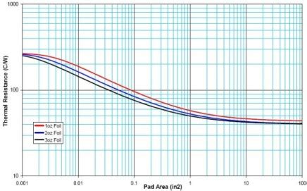
- Copper thickness and distribution: Thicker copper traces and larger copper areas help to spread heat more effectively.
- Component placement: The location and spacing of components on the board can affect heat dissipation.
- Airflow: Adequate airflow across the board helps to remove heat from the surface.
Calculating PCB Thermal Resistance
To calculate the thermal resistance of a PCB, you need to know the temperature difference between two points on the board (ΔT) and the power dissipated between those points (P). The thermal resistance (Rth) is then given by:
Rth = ΔT / P
For example, if the temperature difference between a component and the ambient air is 20°C, and the component is dissipating 1 watt of power, the thermal resistance would be:
Rth = 20°C / 1W = 20°C/W
Thermal Resistance of PCB Materials
The thermal resistance of a PCB is largely determined by the thermal conductivity of the substrate material. Some common PCB substrate materials and their thermal conductivities are shown in the table below:
| Material | Thermal Conductivity (W/m·K) |
|---|---|
| FR-4 | 0.3 |
| Aluminum | 205 |
| Copper | 401 |
As you can see, copper and aluminum have much higher thermal conductivities than FR-4, making them better choices for high-power applications where heat dissipation is critical.
Designing for Low Thermal Resistance
To minimize thermal resistance and improve heat dissipation in a PCB design, consider the following strategies:
1. Choose High-Conductivity Materials
Using substrate materials with high thermal conductivity, such as aluminum or copper-clad laminates, can significantly reduce thermal resistance. For example, an aluminum-backed PCB can have a thermal resistance up to 10 times lower than an equivalent FR-4 board.
2. Increase Copper Thickness and Area
Thicker copper traces and larger copper areas, such as ground planes and heat spreaders, help to distribute heat more evenly across the board. This can be achieved by using thicker copper foil during fabrication or by adding additional copper layers to the stackup.
3. Optimize Component Placement
Placing high-power components away from heat-sensitive devices and spacing them apart can help to minimize localized hot spots. Components should also be oriented to allow for maximum airflow across their surfaces.
4. Use Thermal Vias
Thermal vias are small holes drilled through the PCB and filled with conductive material, such as copper or solder. They provide a low-resistance path for heat to flow from the component side of the board to the opposite side, where it can be dissipated by a heatsink or other cooling solution.
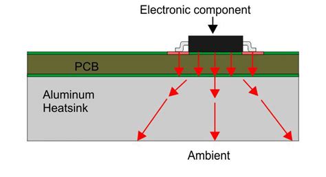
5. Incorporate Heatsinks and Cooling Solutions
For high-power applications, it may be necessary to use external cooling solutions such as heatsinks, fans, or liquid cooling systems. These can be attached directly to the PCB or to individual components to help remove heat from the system.

Measuring PCB Thermal Resistance
To verify that a PCB design meets its thermal requirements, it is important to measure its thermal resistance under actual operating conditions. This can be done using various methods, including:
1. Thermocouples
Thermocouples are temperature sensors that can be attached directly to the PCB or individual components. They provide a simple and accurate way to measure surface temperatures at specific points on the board.
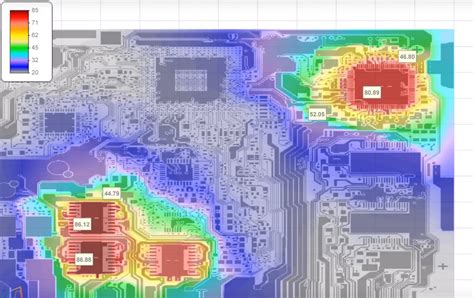
2. Infrared Cameras
Infrared cameras can be used to capture thermal images of the entire PCB, showing the temperature distribution across its surface. This can help to identify hot spots and areas of high thermal resistance.
3. Thermal Simulation Software
Thermal simulation software, such as ANSYS or SolidWorks, can be used to model the thermal behavior of a PCB design before it is fabricated. This allows designers to optimize the layout and materials for better heat dissipation and to identify potential thermal issues early in the design process.
Real-World Applications
PCB thermal resistance is a critical consideration in many real-world applications, particularly those involving high-power electronics or harsh environmental conditions. Some examples include:
1. Power Electronics
Power electronic devices, such as motor drives, inverters, and power supplies, generate significant amounts of heat during operation. Designing these systems with low thermal resistance helps to ensure reliable performance and long-term durability.
2. Automotive Electronics
Automotive electronics, such as engine control modules and infotainment systems, must operate reliably in a wide range of temperature and humidity conditions. Using high-conductivity materials and optimized layouts can help to minimize thermal resistance and improve the robustness of these systems.
3. Aerospace and Defense
Aerospace and defense applications often require electronics to operate in extreme environments, such as high altitudes, high temperatures, or vacuum conditions. Designing PCBs with low thermal resistance is critical to ensuring the reliability and performance of these systems.
FAQ
1. What is the difference between thermal resistance and thermal conductivity?
Thermal resistance is a measure of a material’s ability to resist heat flow, while thermal conductivity is a measure of its ability to conduct heat. Thermal resistance is expressed in units of °C/W, while thermal conductivity is expressed in units of W/m·K.
2. How does PCB thickness affect thermal resistance?
In general, thinner PCBs have higher thermal resistance than thicker boards. This is because there is less material available to conduct heat away from the components. However, using high-conductivity materials or incorporating thermal vias can help to mitigate this effect.
3. Can I use thermal resistance values from datasheets in my PCB design?
Thermal resistance values provided in component datasheets are typically measured under ideal conditions and may not accurately reflect the performance of the component in a real-world PCB design. It is important to verify the thermal resistance of your PCB through measurement or simulation to ensure that it meets your design requirements.
4. What is the impact of high thermal resistance on PCB reliability?
High thermal resistance can lead to elevated component temperatures, which can accelerate aging and increase the risk of failure. Over time, this can result in reduced reliability and shorter product lifespans. Designing for low thermal resistance helps to minimize these risks and improve overall system reliability.
5. How can I reduce the thermal resistance of an existing PCB design?
If an existing PCB design has high thermal resistance, there are several strategies you can use to improve its performance:
- Add thermal vias to provide a low-resistance path for heat to flow through the board.
- Increase the thickness or area of copper traces and planes to improve heat spreading.
- Use thermal interface materials, such as thermal pads or paste, to improve heat transfer between components and the PCB.
- Incorporate heatsinks or other cooling solutions to remove heat from the system more effectively.
By understanding the factors that influence PCB thermal resistance and designing with heat dissipation in mind, engineers can create more reliable and robust electronic systems that can withstand the demands of today’s high-performance applications.
No responses yet