Introduction to PCB Substrate
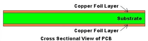
PCB substrate is the foundational material upon which printed circuit boards (PCBs) are built. It provides the necessary mechanical support and electrical insulation for the conductive copper traces, components, and other features that make up a functional PCB. The choice of substrate material significantly impacts the performance, reliability, and cost of the final product.
Types of PCB Substrates
There are several types of PCB substrates available, each with its own unique properties and advantages. The most common types include:
- FR-4
- High-Frequency Laminates
- Metal Core PCBs
- Flexible PCBs
- Ceramic PCBs
FR-4 Substrate
FR-4 is the most widely used PCB substrate material. It is a composite material made of woven fiberglass cloth impregnated with an epoxy resin binder. FR-4 offers good mechanical strength, electrical insulation, and thermal stability, making it suitable for a wide range of applications.
| Property | Value |
|---|---|
| Dielectric Constant | 4.2-4.5 |
| Dissipation Factor | 0.02 |
| Thermal Conductivity | 0.3 W/mK |
| Glass Transition Temperature | 130-140°C |
High-Frequency Laminates
High-frequency laminates are designed for use in applications that require superior electrical performance at high frequencies, such as RF and microwave circuits. These substrates typically have a lower dielectric constant and dissipation factor compared to FR-4, which helps minimize signal loss and distortion.
Some popular high-frequency laminates include:
- Rogers RO4000 series
- Isola IS680
- Taconic RF-35
Metal Core PCBs
Metal core PCBs (MCPCBs) feature a metal base layer, usually aluminum, which serves as a heat spreader. This substrate is ideal for applications that generate significant heat, such as high-power LED lighting and power electronics. The metal core helps dissipate heat more efficiently, improving the thermal management of the circuit.
Flexible PCBs
Flexible PCBs use a flexible polymer substrate, such as polyimide or polyester, to create circuits that can bend, fold, or twist. This makes them ideal for applications where space is limited or where the PCB needs to conform to a specific shape, such as in wearable electronics, medical devices, and aerospace systems.
Ceramic PCBs
Ceramic PCBs use a ceramic material, typically alumina (Al2O3), as the substrate. Ceramic substrates offer excellent thermal conductivity, high dielectric strength, and low dielectric loss, making them suitable for high-temperature and high-frequency applications. However, they are more expensive and brittle compared to other substrate materials.
Factors to Consider When Choosing a PCB Substrate
When selecting a PCB substrate for your application, consider the following factors:
- Electrical Properties
- Dielectric constant
- Dissipation factor
- Dielectric strength
-
Electrical conductivity
-
Thermal Properties
- Thermal conductivity
- Glass transition temperature
-
Coefficient of thermal expansion (CTE)
-
Mechanical Properties
- Flexural strength
- Tensile strength
- Dimensional stability
-
Moisture absorption
-
Frequency Requirements
- High-frequency performance
-
Signal integrity
-
Environmental Factors
- Operating temperature range
- Humidity resistance
-
Chemical resistance
-
Cost and Availability
- Material cost
- Manufacturing process compatibility
- Lead time and minimum order quantity

PCB Substrate Manufacturing Process
The manufacturing process for PCB substrates typically involves the following steps:
- Raw Material Preparation
- Mixing of resin and other additives
-
Impregnation of reinforcement materials (e.g., fiberglass)
-
Prepreg Manufacturing
- Coating of resin-impregnated reinforcement onto a carrier film
-
Drying and partial curing of the prepreg
-
Lamination
- Stacking of prepreg layers and copper foils
-
Pressing under heat and pressure to form a solid laminate
-
Curing
-
Final curing of the laminate to achieve desired properties
-
Copper Etching
-
Removal of unwanted copper to create circuit patterns
-
Finishing
- Application of solder mask, silkscreen, and surface finishes

Advanced PCB Substrate Technologies
As the demand for higher performance and more compact electronics grows, new PCB substrate technologies are being developed to meet these challenges. Some of the advanced substrate technologies include:
High-Density Interconnect (HDI) Substrates
HDI substrates feature finer pitch and smaller via sizes, allowing for higher component density and improved signal integrity. These substrates often use advanced materials, such as low-loss dielectrics and ultra-thin laminates, to achieve the required performance.
Embedded Component Substrates
Embedded component substrates integrate passive components, such as resistors and capacitors, directly into the PCB substrate. This approach saves space on the board surface and reduces parasitic effects, enabling more compact and efficient designs.
3D-Printed PCB Substrates
3D printing technology is being explored for the fabrication of PCB substrates with complex geometries and unique properties. This approach enables the creation of customized substrates with integrated features, such as cooling channels and shielding structures, which are difficult to achieve with traditional manufacturing methods.

Frequently Asked Questions (FAQ)
- What is the most common PCB substrate material?
-
FR-4 is the most widely used PCB substrate material due to its good balance of mechanical, electrical, and thermal properties, as well as its relatively low cost.
-
Can I use a flexible PCB substrate for high-temperature applications?
-
Flexible PCB substrates, such as polyimide, can withstand higher temperatures compared to traditional FR-4. However, for extreme high-temperature applications, ceramic substrates may be a better choice.
-
How does the choice of PCB substrate affect signal integrity?
-
The substrate’s dielectric constant and dissipation factor play a crucial role in signal integrity. Lower values of these properties help minimize signal loss and distortion, especially at high frequencies.
-
What are the advantages of using a metal core PCB substrate?
-
Metal core PCB substrates offer improved thermal management by efficiently dissipating heat from the circuit. This makes them ideal for applications with high power densities, such as LED lighting and power electronics.
-
Are there eco-friendly alternatives to traditional PCB substrates?
- Yes, there are eco-friendly PCB Substrate Materials available, such as halogen-free FR-4 and biodegradable polymers. These materials aim to reduce the environmental impact of PCB manufacturing and disposal.
Conclusion
PCB substrate selection is a critical aspect of PCB design and manufacturing. Understanding the properties, advantages, and limitations of different substrate materials is essential for choosing the most suitable option for your specific application. By considering factors such as electrical performance, thermal management, mechanical stability, and cost, you can ensure that your PCB substrate choice aligns with your project requirements and contributes to the overall success of your electronic device.
No responses yet