Understanding BGA Packages
Before diving into fanout options, it’s important to understand the basics of BGA packages. A BGA is a surface-mount package that uses an array of solder balls on the bottom of the component to connect to the PCB. BGAs offer several advantages over other package types, such as:
- High pin count density
- Excellent thermal and electrical performance
- Reduced package size
- Improved signal integrity
However, BGAs also present unique challenges for PCB design and manufacturing. The high pin count and small pitch of BGA packages require careful planning and precise routing techniques to ensure proper connectivity and signal integrity.
BGA Fanout Options
There are several fanout options available when routing a BGA, each with its own advantages and disadvantages. The choice of fanout strategy depends on factors such as the BGA package size, pin count, pitch, PCB layer stackup, and signal requirements. Let’s explore some common BGA fanout options:
1. Via-in-Pad (VIP)
Via-in-pad (VIP) is a fanout technique where vias are placed directly on the BGA pads. This allows for a direct connection between the BGA balls and the inner layers of the PCB, reducing the need for additional routing layers. VIP is often used for high-density BGAs with small pitches, as it provides the shortest path between the BGA and the PCB.
Advantages:
– Minimizes the number of routing layers required
– Reduces the overall PCB size
– Improves signal integrity by minimizing trace lengths
Disadvantages:
– Requires precise via placement and drilling
– May increase manufacturing complexity and cost
– Limits the ability to probe or rework the BGA pads
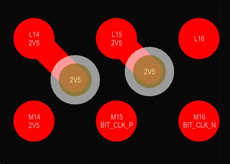
2. Dog-Bone Fanout
Dog-bone fanout, also known as teardrop fanout, is a technique where short traces are used to connect the BGA pads to nearby vias. The traces resemble a dog bone shape, with the via located at one end and the BGA pad at the other. Dog-bone fanout is commonly used for BGAs with moderate pin counts and pitches.
Advantages:
– Provides more flexibility in via placement compared to VIP
– Allows for easier probing and reworking of the BGA pads
– Suitable for a wider range of BGA packages and PCB designs
Disadvantages:
– Requires additional routing space around the BGA
– May increase the overall PCB size
– Can introduce signal integrity issues if traces are too long
3. Through-Via Fanout
Through-via fanout involves placing vias on the outer edges of the BGA pad matrix and routing traces from the BGA pads to the vias. This technique is often used for larger BGAs with higher pin counts and pitches, as it allows for more space between the vias and the BGA pads.
Advantages:
– Provides ample space for via placement and trace routing
– Reduces the risk of manufacturing defects
– Allows for easier inspection and rework of the BGA connections
Disadvantages:
– Requires more routing layers compared to VIP or dog-bone fanout
– Increases the overall PCB size
– May introduce longer trace lengths, impacting signal integrity

Choosing the Right Fanout Strategy
Selecting the appropriate fanout strategy for your BGA depends on several factors. Here are some guidelines to help you make an informed decision:
- Consider the BGA package size and pitch:
- For small BGAs with pitches of 0.5mm or less, VIP fanout is often the best choice.
- For moderate-sized BGAs with pitches between 0.5mm and 0.8mm, dog-bone fanout is a suitable option.
-
For larger BGAs with pitches above 0.8mm, through-via fanout provides more flexibility.
-
Evaluate the PCB layer stackup:
- If the PCB has a limited number of layers, VIP fanout can help minimize the layer count.
-
For multi-layer PCBs, dog-bone or through-via fanout can be used to optimize routing and signal integrity.
-
Assess the signal requirements:
- For high-speed signals, minimizing trace lengths and avoiding sharp bends is crucial. VIP or dog-bone fanout with carefully placed vias can help achieve this.
-
For lower-speed signals, through-via fanout may be sufficient and provide more routing flexibility.
-
Consider manufacturability and cost:
- VIP fanout requires precise via drilling and placement, which can increase manufacturing complexity and cost.
- Dog-bone and through-via fanout are generally easier to manufacture and more cost-effective.
Here’s a comparison table of the different fanout options:
| Fanout Option | BGA Size/Pitch | Layer Count | Signal Integrity | Manufacturability |
|---|---|---|---|---|
| Via-in-Pad | Small/≤0.5mm | Low | Excellent | Complex |
| Dog-Bone | Moderate/0.5-0.8mm | Moderate | Good | Moderate |
| Through-Via | Large/>0.8mm | High | Moderate | Easy |

BGA Fanout Routing Tips
Once you have chosen the appropriate fanout strategy for your BGA, follow these routing tips to ensure optimal performance and manufacturability:
- Use a grid-based routing approach:
- Align the BGA pads and vias to a consistent grid to simplify routing and improve manufacturability.
-
Choose a grid size that matches the BGA pitch and the PCB design rules.
-
Minimize trace lengths and layer transitions:
- Keep traces as short as possible to minimize signal integrity issues and reduce the overall PCB size.
-
Avoid unnecessary layer transitions, as they can introduce signal degradation and increase manufacturing complexity.
-
Provide adequate clearance and spacing:
- Ensure sufficient clearance between traces, vias, and other components to avoid manufacturing defects and signal interference.
-
Follow the PCB manufacturer’s design rules and guidelines for minimum spacing and clearance requirements.
-
Use symmetrical fanout patterns:
- Implement symmetrical fanout patterns whenever possible to ensure even signal distribution and minimize skew.
-
Symmetrical routing also helps with PCB assembly and inspection.
-
Optimize via placement and design:
- Place vias strategically to minimize trace lengths and layer transitions.
-
Use appropriate via sizes and pad sizes based on the PCB manufacturing capabilities and design requirements.
-
Consider signal integrity and impedance matching:
- Route high-speed signals with controlled impedance and matched lengths to maintain signal integrity.
-
Use differential pairs for high-speed differential signals and ensure proper spacing and coupling between the traces.
-
Collaborate with the PCB manufacturer:
- Communicate your BGA fanout strategy and routing requirements to the PCB manufacturer early in the design process.
- Seek their feedback and recommendations to ensure manufacturability and reliability of the PCB.

Frequently Asked Questions (FAQ)
- What is BGA fanout, and why is it important?
-
BGA fanout refers to the pattern of traces and vias that connect the BGA pads to the rest of the circuit. It is important because it directly impacts the signal integrity, manufacturability, and reliability of the PCB.
-
How do I choose the right BGA fanout strategy for my design?
-
Consider factors such as the BGA package size, pitch, PCB layer stackup, and signal requirements. Use the guidelines provided in this article to select the most appropriate fanout option for your specific design.
-
What are the advantages and disadvantages of Via-in-Pad (VIP) fanout?
- Advantages: VIP fanout minimizes the number of routing layers required, reduces the overall PCB size, and improves signal integrity by minimizing trace lengths.
-
Disadvantages: VIP fanout requires precise via placement and drilling, may increase manufacturing complexity and cost, and limits the ability to probe or rework the BGA pads.
-
How can I ensure optimal signal integrity when routing BGA fanouts?
-
Minimize trace lengths and layer transitions, provide adequate clearance and spacing, use symmetrical fanout patterns, optimize via placement and design, and consider impedance matching for high-speed signals.
-
Why is it important to collaborate with the PCB manufacturer during the BGA fanout design process?
- Collaborating with the PCB manufacturer helps ensure that your BGA fanout strategy and routing requirements are manufacturable and reliable. Their feedback and recommendations can help optimize your design and avoid potential issues during fabrication and assembly.
Conclusion
Navigating through BGA fanout options and routing techniques can be challenging, but with the right knowledge and approach, you can design PCBs that are reliable, manufacturable, and meet your specific requirements. By understanding the different fanout strategies, choosing the appropriate option based on your design factors, and following best practices for routing, you can successfully route BGA fanouts and ensure optimal performance of your PCB.
Remember to collaborate with your PCB manufacturer throughout the design process, seeking their input and recommendations to avoid potential issues and optimize your design. With careful planning and execution, you can confidently navigate your way through BGA fanout options and achieve successful PCB designs.

No responses yet