Introduction
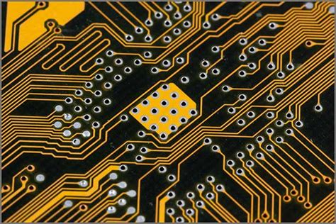
Printed Circuit Boards (PCBs) are the backbone of modern electronics, providing a platform for interconnecting electronic components and enabling complex circuitry. The performance of a PCB is heavily influenced by the properties of the substrate material used in its construction. In this article, we will explore the various substrate properties that impact PCB performance and discuss how to select the right material for your application.
What is a PCB Substrate?
A PCB substrate is the base material upon which the copper traces, pads, and other features are built. It provides mechanical support, electrical insulation, and a stable platform for the components. The substrate is typically made from a dielectric material, which is an insulator that can be polarized by an applied electric field.
Common PCB Substrate Materials
There are several common materials used for PCB substrates, each with its own set of properties and advantages. Some of the most widely used materials include:
- FR-4
- High-Frequency Laminates
- Polyimide
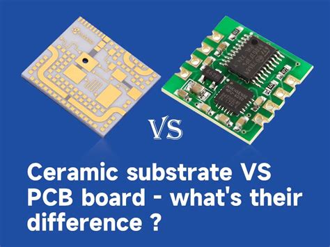
- Ceramic
- Metal Core
Key Substrate Properties
When selecting a PCB substrate material, there are several key properties to consider that can impact the performance of your circuit. These properties include:
Dielectric Constant (Dk)
The dielectric constant, also known as relative permittivity, is a measure of a material’s ability to store electrical energy in an electric field. It is the ratio of the permittivity of the material to the permittivity of free space. A lower dielectric constant is generally preferred for high-frequency applications, as it results in faster signal propagation and reduced signal loss.
| Material | Dielectric Constant (Dk) |
|---|---|
| FR-4 | 4.2 – 4.5 |
| Rogers 4003C | 3.38 |
| Polyimide | 3.4 – 3.5 |
| Alumina (Ceramic) | 9.8 – 10.0 |
Dissipation Factor (Df)
The dissipation factor, also known as loss tangent, is a measure of a material’s ability to dissipate electrical energy as heat. A lower dissipation factor is desirable for high-frequency applications, as it results in lower signal loss and better signal integrity.
| Material | Dissipation Factor (Df) |
|---|---|
| FR-4 | 0.02 |
| Rogers 4003C | 0.0027 |
| Polyimide | 0.002 – 0.003 |
| Alumina (Ceramic) | 0.0001 – 0.0004 |
Thermal Conductivity
Thermal conductivity is a measure of a material’s ability to conduct heat. A higher thermal conductivity is beneficial for applications that generate significant heat, as it helps to dissipate heat away from components and prevent thermal damage.
| Material | Thermal Conductivity (W/mK) |
|---|---|
| FR-4 | 0.3 – 0.4 |
| Aluminum | 205 – 230 |
| Copper | 385 – 400 |
| Alumina (Ceramic) | 20 – 30 |
Coefficient of Thermal Expansion (CTE)
The coefficient of thermal expansion is a measure of how much a material expands or contracts with changes in temperature. A mismatch in CTE between the substrate and components can lead to mechanical stress and failure. It is important to select a substrate material with a CTE that closely matches that of the components.
| Material | CTE (ppm/°C) |
|---|---|
| FR-4 | 12 – 16 |
| Copper | 17 |
| Aluminum | 23 |
| Alumina (Ceramic) | 6.5 – 7.5 |
Mechanical Strength
The mechanical strength of a substrate material determines its ability to withstand physical stress and maintain its shape. This is particularly important for applications that require high reliability or are subject to mechanical shocks and vibrations.
| Material | Tensile Strength (MPa) | Flexural Strength (MPa) |
|---|---|---|
| FR-4 | 310 – 380 | 415 – 480 |
| Polyimide | 90 – 160 | 180 – 280 |
| Alumina (Ceramic) | 260 – 300 | 345 – 380 |

Substrate Selection Considerations
When selecting a PCB substrate material, there are several factors to consider based on your application requirements:
-
Frequency: For high-frequency applications, choose materials with low dielectric constant and dissipation factor to minimize signal loss and distortion.
-
Thermal Management: If your application generates significant heat, select materials with high thermal conductivity to dissipate heat effectively.
-
Mechanical Requirements: Consider the mechanical strength and CTE of the substrate material to ensure it can withstand the physical stresses of your application.
-
Cost: Substrate materials vary in cost, with high-performance materials generally being more expensive. Balance your performance requirements with cost considerations.
-
Manufacturing Complexity: Some substrate materials may require specialized manufacturing processes or have limitations on feature sizes and tolerances. Consider the manufacturability of your design when selecting a substrate.
PCB Substrate Properties and Signal Integrity
The substrate properties have a significant impact on signal integrity in high-speed PCB designs. Signal integrity refers to the ability of a signal to maintain its intended characteristics as it propagates through the circuit. Some key considerations for signal integrity include:
Impedance Control
Maintaining consistent impedance throughout the signal path is crucial for preventing reflections and ensuring proper signal termination. The dielectric constant and thickness of the substrate material influence the characteristic impedance of the traces.
Signal Loss
Signal loss occurs due to the dissipation of electrical energy as heat. The dissipation factor of the substrate material contributes to signal loss, particularly at high frequencies. Choosing a material with a low dissipation factor helps to minimize signal loss.
Crosstalk
Crosstalk is the unintended coupling of signals between adjacent traces. It can be minimized by selecting a substrate material with a low dielectric constant, which reduces the capacitive coupling between traces. Proper trace spacing and shielding techniques can also help to mitigate crosstalk.
Thermal Management
Thermal management is essential for maintaining signal integrity in high-power applications. Substrates with high thermal conductivity help to dissipate heat away from components and prevent thermal-induced signal degradation.
Advanced Substrate Materials
In addition to the common substrate materials discussed earlier, there are several advanced materials that offer unique properties for specialized applications:
-
Low-Temperature Co-fired Ceramic (LTCC): LTCC is a multilayer ceramic substrate that offers excellent high-frequency performance and thermal stability. It is commonly used in RF and microwave applications.
-
High-Temperature Co-fired Ceramic (HTCC): HTCC is similar to LTCC but offers even higher temperature stability and is used in harsh environment applications.
-
Liquid Crystal Polymer (LCP): LCP is a high-performance thermoplastic material that offers excellent electrical properties, low moisture absorption, and high dimensional stability. It is suitable for high-frequency and flexible PCB applications.
-
Teflon (PTFE): Teflon is a fluoropolymer material known for its low dielectric constant, low dissipation factor, and high temperature resistance. It is commonly used in microwave and radar applications.
Frequently Asked Questions (FAQ)
- What is the most commonly used PCB substrate material?
-
FR-4 is the most widely used PCB substrate material due to its good balance of electrical, mechanical, and thermal properties, as well as its cost-effectiveness.
-
Can I mix different substrate materials in the same PCB?
-
Yes, it is possible to use different substrate materials in different layers of a multi-layer PCB. This technique is called hybrid construction and is used to optimize the performance of specific layers while managing costs.
-
How does the substrate thickness affect PCB performance?
-
The substrate thickness influences the characteristic impedance of the traces and the overall mechanical strength of the PCB. Thinner substrates allow for finer trace widths and spacing but may be more susceptible to mechanical stress.
-
What substrate material is best for high-frequency applications?
-
For high-frequency applications, substrate materials with low dielectric constant and dissipation factor, such as Rogers 4003C, Teflon, or LTCC, are preferred to minimize signal loss and distortion.
-
How do I choose the right substrate material for my application?
- When selecting a substrate material, consider your application’s requirements for frequency, thermal management, mechanical strength, and cost. Consult with PCB manufacturers and material suppliers to identify the best material for your specific needs.
Conclusion
The selection of the right PCB substrate material is crucial for ensuring optimal performance, reliability, and cost-effectiveness of your electronic devices. By understanding the key substrate properties and their impact on PCB performance, you can make informed decisions when designing and manufacturing your PCBs.
Consider factors such as dielectric constant, dissipation factor, thermal conductivity, CTE, and mechanical strength when evaluating substrate materials. Additionally, keep signal integrity, thermal management, and manufacturing complexity in mind during the selection process.
By carefully selecting the appropriate substrate material and working closely with PCB manufacturers and material suppliers, you can achieve the best possible performance and reliability for your PCB-based electronic devices.
No responses yet