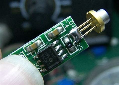
Introduction to LM358 Op Amp
The LM358 is a dual operational amplifier (op amp) integrated circuit designed for general-purpose applications. This versatile and cost-effective component is widely used in various analog circuits, such as signal conditioning, filtering, and amplification. The LM358’s key features include:
- Dual op amp in a single package
- Wide supply voltage range (3V to 32V)
- Low input bias current
- High input voltage range
- Output short-circuit protection
Applications of LM358 Op Amp
The LM358 op amp finds applications in a wide range of electronic projects, including:
- Audio amplification
- Sensor signal conditioning
- Voltage comparators
- Active filters
- Instrumentation amplifiers
PCB Layout Considerations for LM358 Op Amp Circuit
When designing a PCB layout for an LM358 op amp circuit, several key factors must be considered to ensure optimal performance and minimize noise and interference.
Power Supply Decoupling
Proper power supply decoupling is essential to reduce noise and ensure stable operation of the LM358 op amp. To achieve this, follow these guidelines:
- Place decoupling capacitors (typically 0.1μF ceramic) as close as possible to the LM358’s power supply pins (V+ and V-).
- Use a larger value capacitor (e.g., 10μF electrolytic) near the power supply entry point on the PCB to filter low-frequency noise.
- Route power supply traces away from sensitive analog signals to minimize crosstalk.
Grounding
A well-designed grounding scheme is crucial for minimizing ground loops and reducing noise in the LM358 op amp circuit. Consider the following:
- Use a single ground plane or a star ground topology to provide a low-impedance return path for currents.
- Separate analog and digital grounds, connecting them at a single point near the power supply.
- Keep ground traces short and wide to minimize resistance and inductance.
Component Placement
Proper component placement helps minimize noise pickup and ensures optimal performance of the LM358 op amp circuit. Follow these guidelines:
- Place the LM358 op amp close to its associated components, such as feedback resistors and capacitors, to minimize trace lengths and reduce stray capacitance.
- Locate sensitive analog components away from noisy digital circuits and power supply components.
- Orient the LM358 op amp to minimize the distance between its inputs and the signal source, reducing the likelihood of noise pickup.
Trace Routing
Careful trace routing is essential to minimize noise and crosstalk in the LM358 op amp circuit. Consider the following:
- Keep analog signal traces as short as possible and away from noisy digital traces and power supply lines.
- Use ground planes or traces to provide shielding between sensitive analog signals and noisy traces.
- Avoid routing traces parallel to each other for long distances to minimize crosstalk.
- Use 45-degree angles instead of 90-degree angles when routing traces to reduce reflections and improve signal integrity.
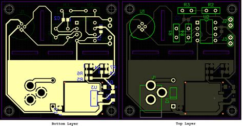
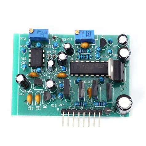
LM358 Op Amp Module PCB Layout
When designing a PCB layout for an LM358 op amp module, the aforementioned considerations should be applied, along with additional factors specific to the module’s functionality and form factor.
Module Functionality
Consider the specific functions and features of the LM358 op amp module when designing the PCB layout. For example:
- If the module includes adjustable gain or filtering options, ensure that the associated components (e.g., potentiometers, jumpers, or DIP switches) are easily accessible and properly labeled.
- If the module requires external connections, such as power supply, input, and output, provide clearly marked and easily accessible connectors or pads.
Form Factor
The PCB layout of the LM358 op amp module should be designed to fit within the desired form factor, whether it is a standalone module or part of a larger system. Consider the following:
- Determine the module’s dimensions and shape based on the enclosure or target system requirements.
- Locate mounting holes and connectors to ensure proper mechanical stability and easy integration with other components or systems.
- If space is limited, consider using surface-mount components (SMD) instead of through-hole components to minimize the module’s footprint.
Electromagnetic Compatibility (EMC)
To ensure that the LM358 op amp module meets electromagnetic compatibility (EMC) requirements, consider the following PCB layout techniques:
- Implement proper grounding and shielding techniques to reduce electromagnetic interference (EMI) and susceptibility.
- Use ground planes or traces to provide a low-impedance return path for high-frequency currents and to minimize loop areas.
- If necessary, include EMI filters, such as ferrite beads or LC filters, on power supply and signal lines to suppress high-frequency noise.

LM358 Op Amp Circuit and Module Testing
After completing the PCB layout and assembly of the LM358 op amp circuit or module, thorough testing is essential to verify its functionality and performance.
Functional Testing
Perform functional tests to ensure that the LM358 op amp circuit or module operates as intended. This may include:
- Verifying the correct amplification or attenuation of input signals.
- Testing the frequency response and bandwidth of the circuit.
- Checking the output voltage range and saturation levels.
- Validating the operation of any adjustable features, such as gain or filtering.
Performance Testing
Conduct performance tests to characterize the LM358 op amp circuit or module’s key parameters and compare them with the datasheet specifications. This may include measuring:
- Input offset voltage
- Input bias current
- Slew rate
- Common-mode rejection ratio (CMRR)
- Power supply rejection ratio (PSRR)
Environmental Testing
If the LM358 op amp module is intended for use in harsh environments or demanding applications, perform environmental tests to ensure its reliability and durability. This may include:
- Temperature cycling tests to verify operation over the specified temperature range.
- Humidity tests to assess the module’s resistance to moisture and condensation.
- Vibration and shock tests to ensure mechanical robustness.
- Electromagnetic compatibility (EMC) tests to verify compliance with relevant EMC standards.
Troubleshooting Common Issues in LM358 Op Amp Circuits
When working with LM358 op amp circuits, you may encounter various issues that can affect the circuit’s performance or functionality. Some common problems and their potential solutions include:
Oscillations or Instability
If the LM358 op amp circuit exhibits oscillations or instability, consider the following:
- Check the power supply decoupling and ensure that the decoupling capacitors are properly sized and placed close to the op amp’s power pins.
- Verify that the feedback network is properly designed and compensated for the desired frequency response.
- Ensure that the op amp’s output is not overloaded or saturated, which can cause instability.
Excessive Noise
If the LM358 op amp circuit suffers from excessive noise, consider the following:
- Review the PCB layout and ensure that proper grounding and shielding techniques are implemented.
- Check for potential sources of electromagnetic interference (EMI) near the circuit and implement appropriate EMI suppression techniques.
- Verify that the op amp’s input signal is not excessively noisy and consider using filters or conditioning circuits to reduce noise.
Incorrect Amplification or Attenuation
If the LM358 op amp circuit does not provide the expected amplification or attenuation, consider the following:
- Double-check the feedback network’s resistor values and ensure they are correctly sized for the desired gain.
- Verify that the op amp’s input and output voltage ranges are not exceeded, as this can cause clipping or distortion.
- Check for any faulty components, such as open or short-circuited resistors or capacitors, that may affect the circuit’s performance.
Conclusion
Designing a PCB layout for an LM358 op amp circuit or module requires careful consideration of various factors, such as power supply decoupling, grounding, component placement, and trace routing. By following best practices and guidelines, you can ensure optimal performance, minimize noise and interference, and achieve reliable operation of your LM358-based designs. Thorough testing and troubleshooting can help identify and resolve any issues, ensuring that your LM358 op amp circuit or module meets the desired specifications and functions as intended.
Frequently Asked Questions (FAQ)
- What is the maximum supply voltage for the LM358 op amp?
-
The LM358 op amp has a wide supply voltage range, typically from 3V to 32V. However, always refer to the specific datasheet for the exact maximum supply voltage rating.
-
Can the LM358 op amp be used in single-supply applications?
-
Yes, the LM358 op amp is well-suited for single-supply applications, as it can operate with input voltages close to the negative supply voltage (ground in single-supply systems).
-
What is the purpose of decoupling capacitors in LM358 op amp circuits?
-
Decoupling capacitors help reduce noise and ensure stable operation of the LM358 op amp by providing a low-impedance path for high-frequency currents and minimizing voltage fluctuations on the power supply lines.
-
How can I reduce noise in my LM358 op amp circuit?
-
To reduce noise in an LM358 op amp circuit, ensure proper power supply decoupling, implement a well-designed grounding scheme, and follow best practices for PCB layout, such as minimizing trace lengths, separating analog and digital signals, and using shielding techniques.
-
What should I do if my LM358 op amp circuit is experiencing oscillations or instability?
- If your LM358 op amp circuit is experiencing oscillations or instability, check the power supply decoupling, verify the feedback network design and compensation, and ensure that the op amp’s output is not overloaded or saturated. Adjusting the feedback network or adding compensation components may help stabilize the circuit.
No responses yet