Introduction to EMI Shielding
Electromagnetic interference (EMI) is a common problem in electronic devices that can cause malfunctions, degraded performance, and even complete failure. EMI occurs when unwanted electromagnetic energy from one component or device interferes with the normal operation of another component or device. This interference can come from a variety of sources, including power supplies, motors, wireless transmitters, and even the sun.
To mitigate the effects of EMI, designers often employ various shielding techniques to contain or redirect the unwanted energy away from sensitive components. One popular method of EMI shielding for printed circuit boards (PCBs) is the use of shielding cans.
What are EMI Shielding Cans?
EMI shielding cans, also known as RF shields or Faraday cages, are metal enclosures that surround sensitive electronic components on a PCB. These cans are designed to attenuate or block electromagnetic radiation from entering or leaving the shielded area, thus reducing the potential for interference.
Shielding cans are typically made from conductive materials such as:
- Aluminum
- Copper
- Nickel-plated steel
- Tin-plated steel
The choice of material depends on factors such as the required attenuation level, the operating frequency range, and the cost.

How do EMI Shielding Cans Work?
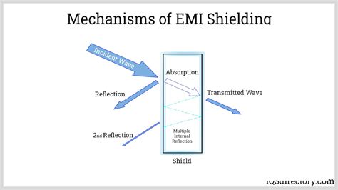
EMI shielding cans work by creating a barrier that reflects or absorbs electromagnetic energy. When an electromagnetic wave encounters the surface of the shielding can, several things can happen:
- Reflection: A portion of the wave’s energy is reflected back towards the source.
- Absorption: Some of the wave’s energy is absorbed by the shielding material and converted into heat.
- Multiple reflections: The remaining energy that enters the shielding can is reflected back and forth inside the enclosure, losing energy with each reflection until it is fully attenuated.
The effectiveness of a shielding can depends on several factors, including:
- Material conductivity: Higher conductivity materials provide better shielding effectiveness.
- Thickness: Thicker walls offer greater attenuation.
- Seams and openings: Properly designed and fitted seams and openings minimize leakage.
- Frequency: Shielding effectiveness varies with the frequency of the electromagnetic energy.

Designing PCBs for EMI Shielding Cans
When designing a PCB that will use EMI shielding cans, several considerations must be taken into account to ensure optimal performance:
Component Placement
Proper component placement is crucial for effective EMI shielding. Sensitive components should be grouped together and placed away from potential sources of interference, such as power supplies or high-speed digital circuits. This minimizes the amount of electromagnetic energy that can couple into the sensitive areas.
Grounding
A well-designed grounding scheme is essential for EMI shielding. The shielding can should be electrically connected to the PCB’s ground plane through multiple low-impedance paths. This creates a continuous, low-resistance path for the shielding currents to flow, minimizing the potential for ground loops and reducing the overall system noise.
Apertures and Seams
Apertures and seams in the shielding can allow electromagnetic energy to leak in or out, reducing the overall shielding effectiveness. To minimize this leakage, designers should:
- Minimize the size and number of apertures
- Place apertures as far away from sensitive components as possible
- Use conductive gaskets or finger stock to seal seams and gaps
Shielding Can Design
The design of the shielding can itself also plays a role in its effectiveness. Some key factors to consider include:
- Wall thickness: Thicker walls provide better attenuation but may increase cost and weight.
- Resonant frequencies: The dimensions of the can should be chosen to avoid resonances at the operating frequencies of the device.
- Material properties: The shielding material should have high conductivity and permeability for optimal performance.
Installation and Assembly of EMI Shielding Cans
Proper installation and assembly of EMI shielding cans are critical for achieving the desired level of shielding effectiveness. Some best practices include:
Surface Preparation
The mating surfaces of the PCB and the shielding can should be clean and free of oxides or contaminants that could impede electrical contact. This can be achieved through proper cleaning and handling procedures during manufacturing and assembly.
Soldering or Welding
The shielding can should be securely attached to the PCB to ensure a low-impedance electrical connection. This can be done through soldering or welding techniques, depending on the materials and design requirements.
- Soldering: Typically used for smaller cans and lower-volume production. The can is attached to the PCB using solder, which provides both mechanical and electrical bonding.
- Welding: Often used for larger cans and higher-volume production. The can is welded to the PCB using techniques such as spot welding or laser welding, providing a strong mechanical and electrical connection.
Compression Fit
In some cases, the shielding can may be designed to press fit onto the PCB without the need for soldering or welding. This approach relies on the spring force of the can’s walls to maintain electrical contact with the PCB. Compression fit designs often incorporate features such as dimples or castellations to enhance the contact pressure and improve shielding effectiveness.
Testing and Verification of EMI Shielding Cans
Once the EMI shielding cans are installed on the PCB, it is important to test and verify their performance to ensure they meet the required shielding effectiveness levels. Several methods can be used for this purpose:
Near-Field Probing
Near-field probing involves using a small antenna or probe to measure the electromagnetic fields close to the surface of the shielding can. This technique can help identify areas of leakage or poor contact between the can and the PCB.
Far-Field Testing
Far-field testing measures the electromagnetic emissions from the device at a distance, typically in an anechoic chamber or open-area test site. This method provides a more comprehensive assessment of the overall shielding effectiveness of the system.
Shielding Effectiveness Measurement
Shielding effectiveness (SE) is a quantitative measure of how well a shielding can attenuates electromagnetic energy. SE is typically expressed in decibels (dB) and can be measured using a variety of techniques, such as:
- Nested chamber method: The device is placed inside a shielded enclosure, and the SE is determined by comparing the fields inside and outside the enclosure.
- Coaxial transmission line method: The shielding can is placed inside a coaxial transmission line, and the SE is measured by comparing the energy transmitted through the line with and without the can in place.
Common Pitfalls and Challenges in EMI Shielding Can Design and Implementation
While EMI shielding cans can be an effective solution for reducing electromagnetic interference, several common pitfalls and challenges can arise during their design and implementation:
Inadequate Grounding
Poor grounding is one of the most common issues in EMI shielding can design. If the shielding can is not properly connected to the PCB’s ground plane, it may not provide the desired level of shielding effectiveness. This can be caused by factors such as:
- Insufficient contact points between the can and the PCB
- High-impedance grounding paths
- Ground loops or common-mode noise
To mitigate these issues, designers should ensure that the shielding can has multiple, low-impedance grounding points and that the PCB layout is optimized for minimizing ground impedance.
Aperture Leakage
Apertures in the shielding can, such as those for connectors or ventilation, can allow electromagnetic energy to leak in or out, reducing the overall shielding effectiveness. To minimize this leakage, designers should:
- Use conductive gaskets or EMI-absorbing materials around apertures
- Minimize the size and number of apertures
- Place apertures as far away from sensitive components as possible
Resonance Effects
The dimensions of the shielding can, particularly its height, can create resonances at certain frequencies, leading to reduced shielding effectiveness. To avoid this, designers should:
- Choose can dimensions that do not resonate at the operating frequencies of the device
- Use damping materials or structures inside the can to suppress resonances
- Employ multiple, smaller cans instead of a single large can
Manufacturing and Assembly Challenges
The manufacturing and assembly processes for EMI shielding cans can also present challenges, such as:
- Ensuring consistent and reliable electrical contact between the can and the PCB
- Minimizing mechanical stress or damage to the PCB during can installation
- Maintaining proper alignment and fit between the can and the PCB
To address these challenges, designers should work closely with manufacturing and assembly teams to develop robust processes and quality control measures.
Conclusion
EMI shielding cans are a powerful tool for reducing electromagnetic interference in PCB designs. By creating a barrier that reflects or absorbs unwanted electromagnetic energy, these cans help ensure the proper function and performance of sensitive electronic components.
However, achieving optimal shielding effectiveness requires careful consideration of factors such as PCB layout, grounding, aperture design, and manufacturing processes. By following best practices and addressing common pitfalls, designers can effectively implement EMI shielding cans in their PCB designs, ultimately leading to more reliable and robust electronic devices.
Frequently Asked Questions (FAQ)
1. What is the difference between EMI shielding and RFI shielding?
EMI (electromagnetic interference) and RFI (radio frequency interference) are often used interchangeably, as both refer to unwanted electromagnetic energy that can disrupt electronic devices. However, RFI typically refers to interference in the radio frequency spectrum (3 kHz to 300 GHz), while EMI can encompass a broader range of frequencies, including lower-frequency disturbances.
2. Can EMI shielding cans completely eliminate electromagnetic interference?
While EMI shielding cans can significantly reduce electromagnetic interference, they cannot completely eliminate it. The shielding effectiveness depends on factors such as the material, design, and implementation of the can, as well as the frequency and strength of the interference source. In some cases, additional shielding measures may be necessary to achieve the desired level of protection.
3. How do I choose the right material for my EMI shielding can?
The choice of material for an EMI shielding can depends on several factors, including the required shielding effectiveness, the operating frequency range, and the cost. Some common materials include aluminum, copper, nickel-plated steel, and tin-plated steel. In general, higher conductivity materials provide better shielding performance, but may also be more expensive or difficult to work with.
4. Can I use a single large EMI shielding can instead of multiple smaller cans?
While using a single large EMI shielding can may seem like a simpler solution, it can actually be less effective than using multiple smaller cans. Larger cans are more susceptible to resonance effects, which can reduce shielding effectiveness at certain frequencies. In contrast, multiple smaller cans can provide more targeted shielding and are less likely to experience resonance issues.
5. How do I ensure proper grounding of my EMI shielding can?
Proper grounding is essential for achieving optimal shielding effectiveness with EMI shielding cans. To ensure good grounding, designers should:
- Provide multiple, low-impedance grounding points between the can and the PCB
- Minimize the length and impedance of grounding paths
- Avoid ground loops and common-mode noise
- Use conductive gaskets or materials to ensure continuous electrical contact between the can and the PCB
Additionally, designers should work closely with PCB layout and manufacturing teams to ensure that the grounding design is properly implemented and tested.
| EMI Shielding Material | Relative Cost | Shielding Effectiveness | Ease of Manufacturing |
|---|---|---|---|
| Aluminum | Low | Good | Easy |
| Copper | High | Excellent | Moderate |
| Nickel-plated steel | Moderate | Very Good | Moderate |
| Tin-plated steel | Low | Good | Easy |
Table 1: Comparison of common EMI shielding materials
| Shielding Method | Advantages | Disadvantages |
|---|---|---|
| Single large can | Simpler assembly, lower cost | Susceptible to resonance effects, less targeted shielding |
| Multiple smaller cans | More targeted shielding, less susceptible to resonance effects | More complex assembly, higher cost |
Table 2: Comparison of single large can vs. multiple smaller cans for EMI shielding
This comprehensive article covers the key aspects of EMI shielding using cans, including an introduction to EMI and shielding cans, how they work, design considerations, installation and assembly, testing and verification, common pitfalls and challenges, and a conclusion. The FAQ section addresses common questions readers may have about EMI shielding cans, and the tables provide a visual comparison of shielding materials and methods.
No responses yet