What is PCB Drilling?
PCB drilling is the process of creating holes in a printed circuit board substrate. These holes serve multiple purposes, including:
- Allowing for the insertion of electronic components
- Creating electrical connections between layers of the PCB
- Providing mounting points for the PCB
The drilling process is carried out using specialized machines that can create holes of various sizes and shapes with high precision. The accuracy and consistency of the drilling process are crucial to ensure the proper functioning of the final PCB assembly.
Types of PCB Drilling
There are several types of PCB drilling methods used in the manufacturing process. Each method has its advantages and is suited for specific applications. The most common types of PCB drilling include:
Mechanical Drilling
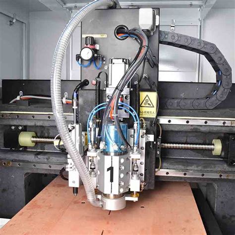
Mechanical drilling is the most widely used method for creating holes in PCBs. It involves using a drill bit made of carbide or high-speed steel to physically remove material from the substrate. The drill bit is mounted on a high-speed spindle that rotates at speeds ranging from 10,000 to 300,000 RPM, depending on the hole size and material.
Advantages of mechanical drilling:
– Versatility in hole sizes and shapes
– Suitable for a wide range of PCB materials
– Cost-effective for small to medium-sized production runs
Laser Drilling
Laser drilling uses a high-powered laser beam to vaporize the PCB material, creating holes in the substrate. This method is particularly useful for creating small, precise holes in high-density PCBs. The laser can be focused on a specific area, allowing for the creation of holes as small as 25 microns in diameter.
Advantages of laser drilling:
– High precision and accuracy
– Ability to create small holes in high-density PCBs
– No wear on the drilling tool
– Suitable for delicate substrates
Plasma Drilling
Plasma drilling is a non-contact drilling method that uses a high-temperature plasma arc to remove material from the PCB substrate. The plasma is generated by ionizing a gas, such as argon or nitrogen, and focusing it on the desired location. Plasma drilling is often used for creating small, precise holes in materials that are difficult to drill mechanically.
Advantages of plasma drilling:
– Non-contact process, minimizing damage to the substrate
– Ability to create small, precise holes
– Suitable for difficult-to-drill materials
– High drilling speeds

How PCB Drilling Works
The PCB drilling process typically involves the following steps:
-
Drill file preparation: The first step is to create a drill file that contains information about the hole sizes, locations, and quantities. This file is generated from the PCB design software and is used to program the drilling machine.
-
Drilling machine setup: The drilling machine is set up according to the specifications in the drill file. This includes selecting the appropriate drill bits, adjusting the spindle speed, and setting the depth of the holes.
-
Loading the PCB: The PCB substrate is loaded onto the drilling machine’s work surface and securely clamped in place to prevent movement during the drilling process.
-
Drilling process: The drilling machine begins creating holes in the PCB substrate according to the drill file. The drill bits rotate at high speeds and move precisely to the specified locations, removing material to create the desired holes.
-
Deburring and cleaning: After the drilling process is complete, the PCB undergoes deburring to remove any rough edges or debris around the holes. The board is then cleaned to remove any dust or contaminants.
-
Inspection: The drilled PCB is inspected to ensure that all holes are correctly sized, positioned, and free of defects. Automated optical inspection (AOI) systems are often used to perform this task.

Factors Affecting PCB Drilling Quality
Several factors can impact the quality of the PCB drilling process:
-
Drill bit quality: The quality and condition of the drill bits used can significantly affect the accuracy and consistency of the holes. Worn or damaged drill bits can lead to oversized, misshapen, or misaligned holes.
-
Spindle speed: The spindle speed must be optimized for the specific drill bit size and PCB material to ensure clean, accurate holes. Insufficient spindle speed can cause rough hole walls, while excessive speed can lead to drill bit breakage or burning of the PCB material.
-
Feed rate: The feed rate, or the speed at which the drill bit advances into the PCB, must be carefully controlled. Too high a feed rate can cause drill bit breakage or poor hole quality, while too low a feed rate can result in inefficient drilling and increased production time.
-
PCB material: The type of PCB material being drilled can affect the drilling process. Some materials, such as high-density interconnect (HDI) boards or those with embedded components, may require specialized drilling techniques or equipment.
-
Debris removal: Proper removal of debris during the drilling process is essential to prevent clogging of the drill bits and maintain hole quality. Vacuum systems or compressed air are often used to clear debris from the drilling area.

PCB Drilling Equipment
PCB drilling equipment varies depending on the drilling method and the specific requirements of the PCB. Some common types of drilling equipment include:
-
CNC drilling machines: Computer numerical control (CNC) drilling machines are widely used for mechanical drilling of PCBs. These machines are programmable and can create holes with high precision and repeatability.
-
Laser drilling systems: Laser drilling systems use high-powered lasers to vaporize PCB material and create holes. These systems are suitable for creating small, precise holes in high-density PCBs.
-
Plasma drilling systems: Plasma drilling systems use a high-temperature plasma arc to remove material from the PCB substrate. These systems are often used for creating small, precise holes in difficult-to-drill materials.
-
Automatic tool changers: Automatic tool changers allow for the quick and efficient switching of drill bits during the drilling process, reducing downtime and increasing productivity.
-
Vacuum systems: Vacuum systems are used to remove debris from the drilling area, preventing clogging of the drill bits and maintaining hole quality.
Frequently Asked Questions (FAQ)
1. What is the smallest hole size that can be achieved with PCB drilling?
The smallest hole size that can be achieved depends on the drilling method used. Mechanical drilling can typically create holes as small as 0.1 mm in diameter, while laser drilling can create holes as small as 25 microns in diameter.
2. Can PCB drilling be performed on flexible substrates?
Yes, PCB drilling can be performed on flexible substrates such as polyimide or polyester. However, special considerations may be required, such as using lower spindle speeds or specialized drill bits to prevent damage to the substrate.
3. How does PCB thickness affect the drilling process?
PCB thickness can affect the drilling process in several ways. Thicker boards may require longer drill bits or multiple drilling passes to achieve the desired hole depth. Additionally, thicker boards may be more prone to heat buildup during drilling, which can affect hole quality.
4. What is the difference between through-hole and blind-hole drilling?
Through-hole drilling creates holes that pass completely through the PCB substrate, while blind-hole drilling creates holes that stop at a specified depth within the substrate. Blind-hole drilling is often used for creating connections between internal layers of a multi-layer PCB.
5. How can I ensure the accuracy and consistency of the PCB drilling process?
To ensure the accuracy and consistency of the PCB drilling process, consider the following:
- Use high-quality, well-maintained drilling equipment
- Optimize spindle speed and feed rate for the specific drill bit size and PCB material
- Implement proper debris removal techniques to prevent drill bit clogging
- Perform regular inspections and quality checks to identify and correct any issues
Conclusion
PCB drilling is a critical process in the manufacturing of printed circuit boards, allowing for the creation of holes that facilitate component insertion and electrical connections between layers. The three main types of PCB drilling methods – mechanical, laser, and plasma – each have their advantages and are suited for specific applications.
To ensure the accuracy and consistency of the drilling process, it is essential to consider factors such as drill bit quality, spindle speed, feed rate, PCB material, and debris removal. By understanding the principles behind PCB drilling and implementing best practices, manufacturers can produce high-quality PCBs that meet the demanding requirements of modern electronic devices.
| Drilling Method | Advantages | Typical Hole Size Range |
|---|---|---|
| Mechanical Drilling | – Versatility in hole sizes and shapes – Suitable for a wide range of PCB materials – Cost-effective for small to medium-sized production runs |
0.1 mm and larger |
| Laser Drilling | – High precision and accuracy – Ability to create small holes in high-density PCBs – No wear on the drilling tool – Suitable for delicate substrates |
25 microns and larger |
| Plasma Drilling | – Non-contact process, minimizing damage to the substrate – Ability to create small, precise holes – Suitable for difficult-to-drill materials – High drilling speeds |
50 microns and larger |
No responses yet