
Understanding PCB Current Capacity
When designing and manufacturing printed circuit boards (PCBs), one of the most crucial factors to consider is the current carrying capacity of the traces. The current capacity of a PCB determines how much electrical current can safely flow through the copper traces without causing damage or overheating. Exceeding the current capacity can lead to a variety of issues, such as:
- Overheating and thermal damage to the PCB and its components
- Reduced performance and reliability of the electronic device
- Increased risk of fire or other safety hazards
To ensure the proper functioning and longevity of your PCB, it is essential to understand the factors that influence current capacity and how to calculate the appropriate trace widths for your design.
Factors Affecting PCB Current Capacity
Several factors can impact the current carrying capacity of a PCB, including:
-
Trace width: Wider traces can handle more current than narrower traces, as they have a larger cross-sectional area for the current to flow through.
-
Copper thickness: The thickness of the copper layer on the PCB also affects current capacity. Thicker copper layers can carry more current than thinner ones.
-
Ambient temperature: Higher ambient temperatures reduce the current capacity of PCB traces, as the heat generated by the current has less opportunity to dissipate.
-
Trace length: Longer traces have higher resistance, which can lead to increased heat generation and reduced current capacity.
-
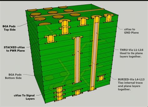
Number of layers: Multi-layer PCBs can distribute current across multiple layers, increasing the overall current capacity compared to single-layer boards.
Calculating PCB Current Capacity
To determine the appropriate trace width for your PCB design, you can use the following formula:
I = k * ΔT^0.44 * A^0.725
Where:
– I = Current capacity in amps (A)
– k = Constant factor (0.048 for external traces, 0.024 for internal traces)
– ΔT = Temperature rise above ambient in °C
– A = Cross-sectional area of the trace in mils^2 (1 mil = 0.001 inch)
To calculate the cross-sectional area (A) of the trace, multiply the trace width by the copper thickness. For example, a trace that is 10 mils wide with a copper thickness of 1 oz/ft² (1.4 mils) would have a cross-sectional area of 14 mils^2.
Here is a table showing the current capacity for various trace widths and copper thicknesses, assuming a temperature rise of 10°C above ambient:
| Trace Width (mils) | Copper Thickness (oz/ft²) | Current Capacity (A) |
|---|---|---|
| 5 | 1 | 0.8 |
| 10 | 1 | 1.3 |
| 20 | 1 | 2.0 |
| 50 | 1 | 3.5 |
| 100 | 1 | 5.5 |
| 5 | 2 | 1.1 |
| 10 | 2 | 1.8 |
| 20 | 2 | 2.8 |
| 50 | 2 | 4.9 |
| 100 | 2 | 7.7 |
Tips for Optimizing PCB Current Capacity
To ensure your PCB can handle the required current without overheating, consider the following tips:
-
Use wider traces for high-current paths, such as power supply lines and ground planes.
-
Choose an appropriate copper thickness for your design. Thicker copper layers can carry more current but may increase manufacturing costs.
-
Minimize trace length whenever possible to reduce resistance and heat generation.
-
Use multiple layers in your PCB design to distribute current and improve heat dissipation.
-
Provide adequate cooling and ventilation for your PCB, especially in high-temperature environments or when dealing with high-current applications.
Temperature Rise and PCB Performance
As electrical current flows through the copper traces on a PCB, it generates heat due to the resistance of the material. This heat can cause the temperature of the PCB and its components to rise, which can have several negative effects on the performance and reliability of the electronic device.
Effects of High Temperatures on PCBs
Excessive temperature rise can lead to various issues, such as:
-
Component degradation: High temperatures can cause components to age faster, reducing their lifespan and potentially leading to premature failure.
-
Solder joint deterioration: Elevated temperatures can cause solder joints to weaken or crack, resulting in intermittent connections or complete failure of the affected components.
-
Warping or delamination: Extreme temperature changes can cause the PCB substrate to warp or the layers to delaminate, compromising the structural integrity of the board.
-
Reduced electrical performance: High temperatures can alter the electrical properties of components and materials, leading to reduced performance or unexpected behavior.
Determining Safe Operating Temperatures
To ensure your PCB operates safely and reliably, it is essential to maintain temperatures within the specified limits for the components and materials used in your design. The maximum safe operating temperature for a PCB depends on several factors, including:
- The temperature ratings of the components used
- The glass transition temperature (Tg) of the PCB substrate material
- The maximum operating temperature specified by the PCB manufacturer
As a general rule, it is recommended to keep the temperature rise of your PCB below 10-15°C above ambient to minimize the risk of thermal damage and ensure optimal performance. However, in some cases, higher temperature rises may be acceptable if the components and materials are rated for the expected operating conditions.

Monitoring and Managing PCB Temperatures
To ensure your PCB operates within safe temperature limits, it is important to monitor and manage the temperatures during the design, prototyping, and production stages.
Thermal Modeling and Simulation
Thermal modeling and simulation tools can help you predict the temperature distribution across your PCB and identify potential hot spots before manufacturing. These tools use mathematical models and finite element analysis (FEA) to calculate the heat generation and dissipation based on the PCB layout, component placement, and expected operating conditions.
By running thermal simulations, you can optimize your PCB design for better heat management, such as:
- Adjusting trace widths and copper thicknesses to improve current capacity
- Rearranging components to minimize heat concentration
- Adding thermal vias or heatsinks to dissipate heat more effectively
Temperature Monitoring During Operation
Once your PCB is manufactured and assembled, it is crucial to monitor the actual temperatures during operation to ensure they remain within safe limits. There are several methods for measuring PCB temperatures, including:
-
Thermocouples: These small, inexpensive sensors can be attached directly to the PCB surface to measure the temperature at specific points.
-
Infrared cameras: Non-contact infrared cameras can provide a visual map of the temperature distribution across the entire PCB, helping you identify hot spots and thermal gradients.
-
Embedded temperature sensors: Some PCBs may include built-in temperature sensors, such as thermistors or digital sensors, which can provide real-time temperature data to the system controller.
By monitoring the PCB temperatures during operation, you can detect any excessive temperature rises and take appropriate actions, such as:
- Adjusting the system’s cooling or ventilation
- Reducing the power consumption or operating frequency of the device
- Implementing thermal throttling or shutdown mechanisms to protect the PCB and its components
Frequently Asked Questions (FAQ)
- What is PCB current capacity, and why is it important?
PCB current capacity refers to the maximum amount of electrical current that can safely flow through the copper traces on a printed circuit board without causing damage or overheating. It is important because exceeding the current capacity can lead to reduced performance, reliability issues, and potential safety hazards.
- How can I calculate the appropriate trace width for my PCB design?
To calculate the appropriate trace width, you can use the formula: I = k * ΔT^0.44 * A^0.725, where I is the current capacity in amps, k is a constant factor (0.048 for external traces, 0.024 for internal traces), ΔT is the temperature rise above ambient in °C, and A is the cross-sectional area of the trace in mils^2. The cross-sectional area is calculated by multiplying the trace width by the copper thickness.
- What factors can affect the current carrying capacity of a PCB?
Several factors can impact the current carrying capacity of a PCB, including trace width, copper thickness, ambient temperature, trace length, and the number of layers in the PCB. Wider traces, thicker copper layers, lower ambient temperatures, shorter traces, and multi-layer designs can all contribute to higher current capacity.
- What are the effects of high temperatures on PCBs, and how can I prevent thermal damage?
High temperatures can cause component degradation, solder joint deterioration, PCB warping or delamination, and reduced electrical performance. To prevent thermal damage, it is recommended to keep the temperature rise of your PCB below 10-15°C above ambient, use appropriate components and materials rated for the expected operating conditions, and implement proper cooling and ventilation measures.
- How can I monitor and manage PCB temperatures during the design and operation stages?
During the design stage, thermal modeling and simulation tools can help predict temperature distribution and identify potential hot spots, allowing you to optimize your PCB layout for better heat management. During operation, you can monitor PCB temperatures using thermocouples, infrared cameras, or embedded temperature sensors, and take appropriate actions such as adjusting cooling, reducing power consumption, or implementing thermal throttling or shutdown mechanisms if necessary.
No responses yet