Table of Contents
- Introduction to PCB Connectors
- Importance of Choosing the Right PCB Connector
- Common PCB Connector Types
- 3.1 Through-Hole Connectors
- 3.2 Surface-Mount Connectors
- 3.3 Board-to-Board Connectors
- 3.4 Wire-to-Board Connectors
- 3.5 Coaxial Connectors
- 3.6 High-Speed Connectors
- 3.7 Power Connectors
- Factors to Consider When Selecting PCB Connectors
- 4.1 Pitch and Spacing
- 4.2 Current Rating
- 4.3 Contact Resistance
- 4.4 Mating Cycles
- 4.5 Environmental Factors
- Popular PCB Connector Manufacturers
- PCB Connector Selection Guide
- Frequently Asked Questions (FAQ)
- Conclusion
1. Introduction to PCB Connectors
PCB connectors are electromechanical components that establish electrical connections between printed circuit boards and other devices or components. They play a vital role in ensuring reliable signal transmission, power delivery, and data communication within electronic systems. PCB connectors come in various types, each designed to cater to specific requirements such as signal integrity, current handling capacity, space constraints, and environmental conditions.

2. Importance of Choosing the Right PCB Connector
Selecting the appropriate PCB connector is crucial for the overall performance, reliability, and longevity of electronic devices. The right connector ensures proper signal integrity, minimizes signal loss, and prevents electromagnetic interference (EMI) and radio frequency interference (RFI). It also facilitates easy assembly, maintenance, and troubleshooting of electronic systems. Choosing the wrong connector can lead to poor performance, signal degradation, and even device failure.

3. Common PCB Connector Types
3.1 Through-Hole Connectors
Through-hole connectors are one of the most common types of PCB connectors. They feature metal pins that are inserted through drilled holes in the PCB and soldered onto the opposite side. Through-hole connectors offer strong mechanical connections and are suitable for high-reliability applications. Examples of through-hole connectors include:
- DIP (Dual In-line Package) Connectors
- Pin Headers
- Screw Terminals
3.2 Surface-Mount Connectors
Surface-mount connectors are designed for surface-mount technology (SMT) assembly processes. They are mounted directly onto the surface of the PCB without requiring through-holes. Surface-mount connectors offer several advantages, such as reduced board space, improved signal integrity, and faster assembly. Some common surface-mount connectors include:
- SMD (Surface-Mount Device) Connectors
- FFC (Flat Flex Cable) Connectors
- FPC (Flexible Printed Circuit) Connectors
3.3 Board-to-Board Connectors
Board-to-board connectors are used to establish electrical connections between two PCBs. They allow for modular designs and facilitate the assembly of complex electronic systems. Board-to-board connectors come in various configurations, such as:
- Mezzanine Connectors
- Stacking Connectors
- Edge Connectors
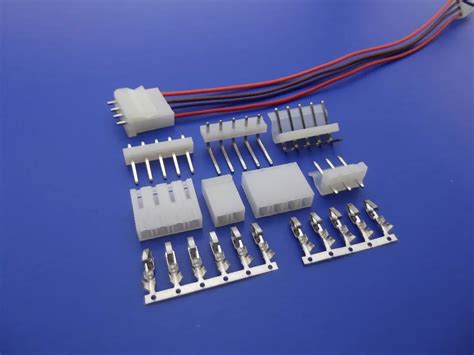
3.4 Wire-to-Board Connectors
Wire-to-board connectors are used to connect wires or cables to PCBs. They provide a reliable and secure connection between the wire and the board, enabling signal and power transmission. Examples of wire-to-board connectors include:
- IDC (Insulation Displacement Connector)
- Crimp Connectors
- Terminal Blocks
3.5 Coaxial Connectors
Coaxial connectors are designed for high-frequency applications, such as RF (Radio Frequency) and microwave systems. They provide excellent signal integrity and shielding against electromagnetic interference. Common coaxial connectors used in PCBs include:
- SMA (SubMiniature version A) Connectors
- SMB (SubMiniature version B) Connectors
- MCX (Micro Coaxial) Connectors
3.6 High-Speed Connectors
High-speed connectors are specifically designed to handle high-speed data transmission while maintaining signal integrity. They are commonly used in applications such as high-speed digital interfaces, telecommunications, and data centers. Examples of high-speed connectors include:
- HDMI (High-Definition Multimedia Interface) Connectors
- USB (Universal Serial Bus) Connectors
- PCIe (Peripheral Component Interconnect Express) Connectors
3.7 Power Connectors
Power connectors are used to deliver electrical power to PCBs and other components. They are designed to handle higher current levels and provide a secure connection for power supply. Some common power connectors used in PCBs include:
- Barrel Connectors
- Molex Connectors
- IEC (International Electrotechnical Commission) Connectors

4. Factors to Consider When Selecting PCB Connectors
When choosing PCB connectors for your electronic projects, several key factors should be taken into account to ensure optimal performance and reliability. These factors include:
4.1 Pitch and Spacing
Pitch refers to the distance between the centers of adjacent pins or contacts in a connector. It is important to select a connector with the appropriate pitch to ensure proper mating and avoid issues such as crosstalk or signal interference. The spacing between pins or contacts also affects the overall size and footprint of the connector on the PCB.
4.2 Current Rating
The current rating of a connector indicates the maximum amount of current it can safely carry without overheating or causing damage. It is crucial to choose a connector with a current rating that matches or exceeds the requirements of your application. Overloading a connector can lead to performance degradation, heat generation, and potential safety hazards.
4.3 Contact Resistance
Contact resistance refers to the electrical resistance between the mating surfaces of a connector. Lower contact resistance is desirable for efficient signal transmission and power delivery. Factors such as contact material, plating, and contact force influence contact resistance. Connectors with gold-plated contacts typically offer lower contact resistance compared to other materials.
4.4 Mating Cycles
Mating cycles represent the number of times a connector can be mated and unmated without compromising its performance or reliability. If your application requires frequent connects and disconnects, it is important to select a connector with a high mating cycle rating. Connectors with robust designs and durable materials can withstand a higher number of mating cycles.
4.5 Environmental Factors
Environmental factors such as temperature, humidity, vibration, and chemical exposure can impact the performance and longevity of PCB connectors. Consider the operating environment of your electronic device and choose connectors that are designed to withstand the specific environmental conditions. Connectors with sealing mechanisms, ruggedized designs, or specialized materials may be necessary for harsh environments.
5. Popular PCB Connector Manufacturers
There are several renowned manufacturers that offer a wide range of PCB connectors for various applications. Some of the popular PCB connector manufacturers include:
- Amphenol
- Molex
- TE Connectivity
- Hirose Electric
- JST
- Samtec
- Harwin
These manufacturers provide high-quality connectors with extensive documentation, technical support, and application-specific solutions.
6. PCB Connector Selection Guide
To help you select the most suitable PCB connector for your project, consider the following steps:
- Determine the signal and power requirements of your application.
- Consider the available space on the PCB and the connector’s footprint.
- Evaluate the environmental conditions and choose connectors with appropriate ratings.
- Assess the mating cycles required and select connectors with suitable durability.
- Review the pitch and spacing of the connector to ensure compatibility with your PCB design.
- Consider the ease of assembly, maintenance, and troubleshooting.
- Consult with the connector manufacturer’s technical support for specific recommendations.
7. Frequently Asked Questions (FAQ)
7.1 What is the difference between through-hole and surface-mount connectors?
Through-hole connectors have metal pins that are inserted through drilled holes in the PCB and soldered onto the opposite side. Surface-mount connectors, on the other hand, are mounted directly onto the surface of the PCB without requiring through-holes. Surface-mount connectors offer advantages such as reduced board space and improved signal integrity.
7.2 How do I determine the current rating of a connector?
The current rating of a connector is typically specified in the manufacturer’s datasheet. It indicates the maximum amount of current the connector can safely carry without overheating or causing damage. When selecting a connector, ensure that its current rating matches or exceeds the requirements of your application.
7.3 What is the importance of contact resistance in PCB connectors?
Contact resistance refers to the electrical resistance between the mating surfaces of a connector. Lower contact resistance is desirable for efficient signal transmission and power delivery. Higher contact resistance can lead to signal loss, voltage drop, and heat generation. Connectors with gold-plated contacts typically offer lower contact resistance compared to other materials.
7.4 How can I choose the right connector for a harsh environment?
When selecting a connector for a harsh environment, consider factors such as temperature range, humidity, vibration, and chemical exposure. Look for connectors with sealing mechanisms, ruggedized designs, or specialized materials that can withstand the specific environmental conditions. Consult with the connector manufacturer’s technical support for recommendations based on your application requirements.
7.5 Can I mix and match connectors from different manufacturers?
While it is possible to mix and match connectors from different manufacturers, it is generally recommended to use connectors from the same manufacturer within a single application. This ensures compatibility, consistent performance, and ease of sourcing. If mixing connectors is necessary, carefully review the specifications and ensure that the connectors are compatible in terms of pitch, spacing, and electrical characteristics.
8. Conclusion
PCB connectors play a vital role in establishing reliable electrical connections within electronic devices. Choosing the right PCB connector is crucial for ensuring optimal performance, signal integrity, and overall system reliability. In this article, we have explored the best list of PCB connector types you should know in 2023, including through-hole connectors, surface-mount connectors, board-to-board connectors, wire-to-board connectors, coaxial connectors, high-speed connectors, and power connectors.
When selecting PCB connectors, consider factors such as pitch and spacing, current rating, contact resistance, mating cycles, and environmental factors. Popular PCB connector manufacturers, such as Amphenol, Molex, and TE Connectivity, offer a wide range of high-quality connectors for various applications.
By understanding the different types of PCB connectors and their specific features, you can make informed decisions and select the most suitable connectors for your electronic projects. Remember to consult with the connector manufacturer’s technical support for specific recommendations and guidance based on your application requirements.
Stay up-to-date with the latest advancements in PCB connector technology to ensure that your electronic devices are equipped with reliable, high-performance connectors that meet the demands of the ever-evolving electronics industry.
No responses yet