What are PCB Connectors?
PCB connectors, also known as printed circuit board connectors, are electromechanical components that establish electrical and mechanical connections between PCBs and other devices or subsystems. They provide a means to transfer power, signals, and data while allowing for easy assembly, disassembly, and reconfiguration of electronic systems.
PCB connectors come in various shapes, sizes, and configurations to suit different applications and requirements. They can be classified based on factors such as the connection method, mounting style, gender, pitch, and number of contacts.
Types of PCB Connectors
There are several types of PCB connectors available in the market, each designed for specific purposes and applications. Let’s explore some of the most common types:
1. Header Connectors
Header connectors are one of the most widely used PCB Connector Types. They consist of a row of male pins that protrude from the PCB and are typically used in conjunction with female receptacles or jumper wires. Header connectors are versatile and can be used for power, signal, or data transmission.
Characteristics of Header Connectors:
- Available in various pitches (e.g., 2.54mm, 2.00mm, 1.27mm)
- Can have single or double rows of pins
- Offers through-hole or surface-mount options
- Suitable for low to medium-density connections
Applications of Header Connectors:
- Microcontroller and development boards
- Prototyping and breadboarding
- Interfacing with sensors, displays, and peripherals
2. Board-to-Board Connectors
Board-to-board (B2B) connectors are used to establish connections between two PCBs that are stacked or placed side by side. They provide a compact and reliable solution for interconnecting multiple PCBs in a system.
Characteristics of Board-to-Board Connectors:
- Available in various heights and pitches
- Can have male-to-male, male-to-female, or hermaphroditic mating
- Offers different stacking heights for PCB spacing
- Supports high-speed and high-density connections
Applications of Board-to-Board Connectors:
- Modular electronic systems
- Compact devices with limited space
- High-density PCB assemblies
3. Card Edge Connectors
Card edge connectors are designed to mate directly with the exposed copper pads on the edge of a PCB, eliminating the need for additional connectors on the board. They provide a simple and cost-effective solution for connecting PCBs to backplanes or motherboards.
Characteristics of Card Edge Connectors:
- Available in various pitches and lengths
- Supports single or double-sided PCB insertion
- Offers high-density connections
- Suitable for hot-swapping and removaBLE Modules
Applications of Card Edge Connectors:
- Expansion cards (e.g., graphics cards, memory modules)
- Backplane systems
- Industrial control systems
4. FFC/FPC Connectors
Flat Flexible Cable (FFC) and Flat Printed Circuit (FPC) connectors are used to connect flexible ribbon cables or flexible printed circuits to PCBs. They provide a low-profile and space-saving solution for connecting components in tight spaces.
Characteristics of FFC/FPC Connectors:
- Thin and lightweight design
- Available in various pitches and contact counts
- Supports ZIF (Zero Insertion Force) or non-ZIF mating
- Suitable for high-density and high-speed connections
Applications of FFC/FPC Connectors:
- Mobile devices and wearables
- Displays and touch screens
- Automotive electronics
5. D-Sub Connectors
D-Sub (D-Subminiature) connectors are widely used for serial communication interfaces, such as RS-232, and for analog video connections. They have a distinctive D-shaped shell that provides mechanical stability and prevents incorrect mating.
Characteristics of D-Sub Connectors:
- Available in various sizes (e.g., DB9, DB15, DB25)
- Offers male and female versions
- Supports through-hole or surface-mount mounting
- Provides shielding and strain relief options
Applications of D-Sub Connectors:
- Serial communication interfaces
- Analog video connections (e.g., VGA)
- Industrial and scientific equipment
6. Modular Connectors
Modular connectors, such as RJ45 (Registered Jack 45) and USB (Universal Serial Bus) connectors, are widely used for Ethernet and USB connectivity, respectively. They provide standardized and reliable connections for data communication and power delivery.
Characteristics of Modular Connectors:
- Standardized form factors and pinouts
- Available in various categories and speeds
- Offers through-hole or surface-mount options
- Provides locking mechanisms for secure mating
Applications of Modular Connectors:
- Ethernet networking
- USB peripherals and devices
- Telecommunications equipment
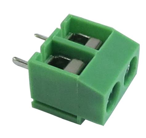
7. Power Connectors
Power connectors are specifically designed for delivering electrical power to PCBs and electronic devices. They come in various forms, such as barrel connectors, terminal blocks, and molex connectors, to suit different power requirements and applications.
Characteristics of Power Connectors:
- Available in various current ratings and voltages
- Offers different contact configurations and locking mechanisms
- Provides polarization and keying features to prevent incorrect mating
- Suitable for high-current and high-voltage applications
Applications of Power Connectors:
- Power supplies and adapters
- Industrial equipment and machinery
- Automotive and aerospace systems

Choosing the Right PCB Connector
When selecting a PCB connector for your project, there are several key factors to consider to ensure optimal performance, reliability, and compatibility. Here are some important considerations:
-
Application Requirements: Understand the specific requirements of your application, such as the operating environment, data rate, power rating, and space constraints. This will help you narrow down the suitable connector types.
-
Pitch and Density: Consider the pitch (distance between contacts) and density of the connector based on your PCB layout and component spacing. Smaller pitches allow for higher density connections but may require more precise manufacturing and assembly.
-
Mounting Style: Decide whether you need through-hole or surface-mount connectors based on your PCB fabrication and assembly processes. Through-hole connectors provide stronger mechanical stability, while surface-mount connectors offer better space savings and automated assembly.
-
Mating Cycles: Evaluate the expected number of mating cycles (insertions and removals) the connector will undergo during its lifetime. Choose connectors with appropriate durability and contact plating to withstand the required mating cycles.
-
Signal Integrity: For high-speed and sensitive signal connections, consider connectors with good signal integrity characteristics, such as controlled impedance, shielding, and crosstalk reduction features.
-
Environmental Factors: Assess the environmental conditions the connector will be exposed to, such as temperature range, humidity, vibration, and chemical exposure. Select connectors with appropriate ratings and materials to withstand these conditions.
-
Compatibility and Standardization: Ensure that the chosen connector is compatible with the mating connectors or cables used in your system. Adhere to industry standards and specifications, such as USB, Ethernet, or PCIe, when applicable.
-
Cost and Availability: Consider the cost of the connectors and their availability from suppliers. Strike a balance between performance, reliability, and cost based on your project’s budget and supply chain requirements.

Frequently Asked Questions (FAQ)
-
Q: What is the difference between through-hole and surface-mount PCB connectors?
A: Through-hole connectors have pins that are inserted into drilled holes on the PCB and soldered in place, providing strong mechanical stability. Surface-mount connectors have leads that are soldered directly onto the PCB surface, offering better space savings and automated assembly compatibility. -
Q: How do I determine the appropriate pitch for my PCB connector?
A: The pitch of a PCB connector depends on factors such as the available space on the PCB, the required contact density, and the manufacturing capabilities. Smaller pitches allow for higher density connections but may require more precise manufacturing and assembly processes. Consider the spacing between components and the PCB layout when selecting the appropriate pitch. -
Q: What are the advantages of using modular connectors like USB and Ethernet?
A: Modular connectors, such as USB and Ethernet, offer standardized and reliable connections for data communication and power delivery. They have well-defined form factors, pinouts, and protocols, ensuring compatibility across different devices and systems. Modular connectors also provide easy plug-and-play connectivity and are widely available in the market. -
Q: How do I ensure signal integrity in high-speed PCB connectors?
A: To ensure signal integrity in high-speed PCB connectors, consider the following factors: - Use connectors with controlled impedance characteristics to match the impedance of the PCB traces and cables.
- Select connectors with shielding features to minimize electromagnetic interference (EMI) and crosstalk.
- Implement proper PCB layout techniques, such as maintaining consistent trace widths, minimizing trace lengths, and avoiding sharp bends.
-
Use differential signaling for high-speed interfaces to reduce noise and improve signal quality.
-
Q: What are the environmental considerations when choosing PCB connectors?
A: When selecting PCB connectors, consider the environmental factors they will be exposed to, such as: - Temperature range: Ensure the connectors can withstand the expected operating and storage temperature range of the application.
- Humidity: Select connectors with appropriate moisture resistance ratings, especially for applications in high-humidity environments.
- Vibration and shock: Choose connectors with robust mechanical designs and locking mechanisms to withstand vibration and shock loads.
- Chemical exposure: Consider the chemical resistance of the connector materials if the application involves exposure to harsh chemicals or solvents.
| Connector Type | Pitch (mm) | Mounting Style | Applications |
|---|---|---|---|
| Header | 2.54, 2.00, 1.27 | Through-hole, Surface-mount | Prototyping, Interfacing |
| Board-to-Board | Various | Surface-mount | Modular systems, High-density assemblies |
| Card Edge | Various | Edge connector | Expansion cards, Backplanes |
| FFC/FPC | Various | ZIF, Non-ZIF | Mobile devices, Displays |
| D-Sub | Various | Through-hole, Surface-mount | Serial communication, Analog video |
| Modular | Standardized | Through-hole, Surface-mount | Ethernet, USB |
| Power | Various | Through-hole, Surface-mount | Power supplies, Industrial equipment |

Conclusion
PCB connectors play a crucial role in establishing reliable electrical and mechanical connections between printed circuit boards and other devices or subsystems. Understanding the different types of PCB connectors, their characteristics, and applications is essential for designing robust and efficient electronic systems.
When selecting PCB connectors, consider factors such as the application requirements, pitch and density, mounting style, mating cycles, signal integrity, environmental factors, compatibility, and cost. By carefully evaluating these aspects, you can choose the most suitable connectors for your specific project needs.
By following best practices in connector selection, PCB layout, and assembly, you can ensure reliable and high-performance connections in your electronic designs. Stay updated with the latest advancements in connector technologies and industry standards to take advantage of improved features and capabilities.
Remember, investing time and effort in selecting the right PCB connectors can greatly contribute to the overall success and reliability of your electronic products.
No responses yet