Introduction to PCB Components
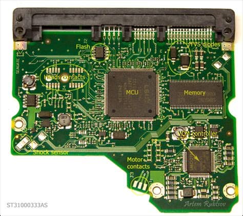
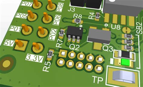
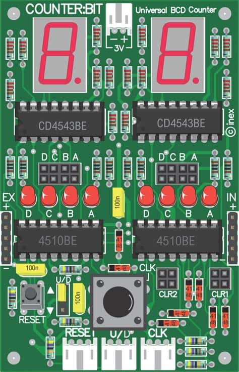
Printed Circuit Boards (PCBs) are the backbone of modern electronics. They provide a platform for mounting and interconnecting electronic components to create functional circuits. A PCB consists of a non-conductive substrate, typically made of fiberglass or other composite materials, with conductive copper traces printed on its surface. These traces form the electrical connections between various components soldered onto the board.
PCBs come in various sizes, shapes, and complexity levels, depending on the application requirements. They can range from simple single-layer boards for basic projects to multi-layer, high-density interconnect (HDI) boards for advanced applications like smartphones, computers, and aerospace systems.
To create a functional PCB, designers must select the appropriate components based on the circuit’s requirements. This article will provide a comprehensive list of common PCB components, their functions, and key specifications to consider when selecting them for your projects.
Types of PCB Components
PCB components can be broadly categorized into two main types:
-
Through-Hole Components: These components have long leads that are inserted through drilled holes in the PCB and soldered on the opposite side. Through-hole components are generally larger and more robust than surface-mount components, making them ideal for high-power applications or situations where mechanical strength is crucial.
-
Surface-Mount Components: These components are directly soldered onto the surface of the PCB without requiring drilled holes. Surface-mount components are smaller and more compact than through-hole components, enabling higher component density and smaller board sizes. They are widely used in modern electronics due to their space-saving advantages and compatibility with automated assembly processes.

Resistors
Resistors are passive components that oppose the flow of electric current in a circuit. They are used to control current, divide voltages, and provide impedance matching. Resistors are available in various types, sizes, and power ratings to suit different applications.
Types of Resistors
-
Carbon Composition Resistors: These resistors are made of a mixture of carbon and ceramic materials. They are inexpensive and have a low temperature coefficient but are less accurate and stable compared to other types.
-
Carbon Film Resistors: These resistors have a thin carbon film deposited on a ceramic substrate. They offer better accuracy and stability than carbon composition resistors and are commonly used in general-purpose applications.
-
Metal Film Resistors: These resistors have a thin metal film, typically nichrome or tantalum nitride, deposited on a ceramic substrate. They provide high accuracy, low noise, and excellent stability, making them suitable for precision applications.
-
Wirewound Resistors: These resistors are made by winding a thin wire, usually nichrome, around a ceramic or fiberglass core. They can handle high power levels and offer good accuracy and stability, but they are larger and more expensive than film resistors.
-
Surface-Mount Resistors: These resistors are designed for surface-mount assembly and come in various package sizes, such as 0402, 0603, 0805, and 1206. They are available in different types, including thick film, thin film, and metal foil, to cater to various accuracy and stability requirements.
Key Specifications for Resistors
When selecting resistors for your PCB, consider the following key specifications:
-
Resistance Value: The resistance value is measured in ohms (Ω) and determines the amount of current the resistor will allow to pass through for a given voltage.
-
Tolerance: Tolerance indicates the allowable variation in the resistor’s actual value compared to its nominal value. Common tolerances include ±1%, ±5%, and ±10%.
-
Power Rating: The power rating specifies the maximum amount of power the resistor can dissipate without damage. It is measured in watts (W) and should be chosen based on the expected current and voltage in the circuit.
-
Temperature Coefficient: The temperature coefficient describes how the resistor’s value changes with temperature. It is expressed in parts per million per degree Celsius (ppm/°C) and is important for applications where temperature stability is critical.
Resistor Selection Table
| Resistor Type | Tolerance | Power Rating | Temperature Coefficient | Applications |
|---|---|---|---|---|
| Carbon Composition | ±5%, ±10% | 0.125W-2W | ±1500 ppm/°C | General purpose, low-cost |
| Carbon Film | ±5%, ±10% | 0.125W-2W | ±200 to ±500 ppm/°C | General purpose, improved stability |
| Metal Film | ±0.1%, ±1%, ±5% | 0.125W-2W | ±50 to ±100 ppm/°C | Precision, low noise, high stability |
| Wirewound | ±1%, ±5% | 1W-100W | ±20 to ±50 ppm/°C | High power, high accuracy |
| Surface-Mount | ±0.1%, ±1%, ±5% | 0.062W-2W | ±25 to ±200 ppm/°C | Compact, automated assembly |

Capacitors
Capacitors are passive components that store electrical energy in an electric field. They are used for filtering, coupling, decoupling, and energy storage in various electronic circuits. Capacitors come in different types, each with unique characteristics and applications.
Types of Capacitors
-
Ceramic Capacitors: These capacitors use a ceramic dielectric material and are available in various package sizes and voltage ratings. They offer high stability, low ESR (Equivalent Series Resistance), and good high-frequency performance, making them suitable for decoupling and high-frequency filtering applications.
-
Electrolytic Capacitors: These capacitors use an electrolyte as the dielectric material and are polarized, meaning they have distinct positive and negative terminals. They offer high capacitance values in a compact size but have higher ESR and leakage current compared to other types. Electrolytic capacitors are commonly used for power supply filtering and low-frequency decoupling.
-
Film Capacitors: These capacitors use a thin plastic film, such as polyester or polypropylene, as the dielectric material. They provide good stability, low ESR, and low leakage current, making them suitable for high-frequency filtering, coupling, and timing applications.
-
Tantalum Capacitors: These capacitors use tantalum pentoxide as the dielectric material and are polarized. They offer high capacitance values in a small package size and have good stability and low leakage current. Tantalum capacitors are often used in power supply filtering and decoupling applications.
-
Mica Capacitors: These capacitors use mica as the dielectric material and offer high stability, low loss, and good high-frequency performance. They are often used in high-voltage, high-frequency, and precision applications, such as RF circuits and oscillators.
Key Specifications for Capacitors
When selecting capacitors for your PCB, consider the following key specifications:
-
Capacitance Value: Capacitance is measured in farads (F) and determines the amount of charge the capacitor can store for a given voltage. Common capacitance values range from picofarads (pF) to microfarads (μF).
-
Voltage Rating: The voltage rating specifies the maximum voltage the capacitor can withstand without damage. It is crucial to select a capacitor with a voltage rating higher than the expected voltage in the circuit.
-
Tolerance: Tolerance indicates the allowable variation in the capacitor’s actual value compared to its nominal value. Common tolerances include ±5%, ±10%, and ±20%.
-
ESR: Equivalent Series Resistance (ESR) represents the capacitor’s inherent resistance, which affects its performance in high-frequency applications. Lower ESR values are desirable for improved high-frequency performance and reduced power loss.
-
Dielectric Type: The dielectric material used in the capacitor determines its temperature stability, voltage dependence, and other characteristics. Common dielectric types include ceramic (C0G, X7R, Y5V), film (polyester, polypropylene), electrolytic (aluminum, tantalum), and mica.
Capacitor Selection Table
| Capacitor Type | Capacitance Range | Voltage Rating | Dielectric Type | Applications |
|---|---|---|---|---|
| Ceramic | 1 pF to 100 μF | 10V to 100V | C0G, X7R, Y5V | Decoupling, filtering, high-frequency |
| Electrolytic | 1 μF to 1000 μF | 6.3V to 450V | Aluminum | Power supply filtering, low-frequency |
| Film | 1 nF to 10 μF | 50V to 630V | Polyester, Polypropylene | Coupling, timing, high-frequency filtering |
| Tantalum | 0.1 μF to 1000 μF | 4V to 50V | Tantalum Pentoxide | Power supply filtering, decoupling |
| Mica | 1 pF to 10 nF | 50V to 2500V | Mica | High-voltage, high-frequency, precision |

Inductors
Inductors are passive components that store energy in a magnetic field when current flows through them. They are used for filtering, energy storage, and impedance matching in various electronic circuits. Inductors come in different types and package sizes to suit different applications.
Types of Inductors
-
Air Core Inductors: These inductors have no core material and consist of a wire wound in a coil shape. They have low inductance values and are suitable for high-frequency applications.
-
Ferrite Core Inductors: These inductors have a ferrite core material, which increases their inductance value and improves their performance. They are commonly used in power supply filtering, EMI suppression, and impedance matching applications.
-
Iron Core Inductors: These inductors have an iron core material, which provides high inductance values and good saturation characteristics. They are often used in low-frequency power electronics and energy storage applications.
-
Surface-Mount Inductors: These inductors are designed for surface-mount assembly and come in various package sizes, such as 0402, 0603, 0805, and 1206. They are available with different core materials, including ceramic, ferrite, and iron, to cater to various inductance and frequency requirements.
Key Specifications for Inductors
When selecting inductors for your PCB, consider the following key specifications:
-
Inductance Value: Inductance is measured in henries (H) and determines the amount of energy the inductor can store in its magnetic field. Common inductance values range from nanohenries (nH) to millihenries (mH).
-
Current Rating: The current rating specifies the maximum current the inductor can handle without saturating or overheating. It is important to select an inductor with a current rating higher than the expected current in the circuit.
-
DC Resistance (DCR): DCR represents the inductor’s resistance to direct current and affects its efficiency and power loss. Lower DCR values are desirable for improved efficiency and reduced power loss.
-
Self-Resonant Frequency (SRF): SRF is the frequency at which the inductor’s parasitic capacitance resonates with its inductance, causing a sharp drop in impedance. It is important to select an inductor with an SRF higher than the operating frequency of the circuit.
-
Temperature Rating: The temperature rating specifies the maximum temperature the inductor can withstand without damage or significant performance degradation. It is crucial to select an inductor with a temperature rating suitable for the expected operating environment.
Inductor Selection Table
| Inductor Type | Inductance Range | Current Rating | Core Material | Applications |
|---|---|---|---|---|
| Air Core | 1 nH to 1 μH | 10 mA to 1 A | None | High-frequency, low-inductance |
| Ferrite Core | 1 μH to 10 mH | 100 mA to 10 A | Ferrite | Power supply filtering, EMI suppression |
| Iron Core | 1 mH to 100 mH | 1 A to 100 A | Iron | Low-frequency power electronics, energy storage |
| Surface-Mount | 1 nH to 10 mH | 10 mA to 10 A | Various | Compact, automated assembly |
Diodes
Diodes are semiconductor devices that allow current to flow in only one direction. They are used for rectification, voltage regulation, protection, and switching in various electronic circuits. Diodes come in different types, each with unique characteristics and applications.
Types of Diodes
-
Rectifier Diodes: These diodes are used for converting alternating current (AC) to direct current (DC). They are available in various voltage and current ratings and are commonly used in power supplies, battery chargers, and motor control circuits.
-
Zener Diodes: These diodes are designed to operate in reverse breakdown mode and maintain a constant voltage across their terminals. They are used for voltage regulation, reference, and protection applications.
-
Schottky Diodes: These diodes have a low forward voltage drop and fast switching speed, making them suitable for high-efficiency rectification and high-frequency applications. They are commonly used in switching power supplies and RF circuits.
-
Light-Emitting Diodes (LEDs): These diodes emit light when forward-biased and are used for indication, display, and lighting applications. They are available in various colors, sizes, and brightness levels.
-
Transient Voltage Suppression (TVS) Diodes: These diodes are designed to protect electronic circuits from voltage spikes and transients. They clamp the voltage to a safe level and divert the excess energy away from sensitive components.
Key Specifications for Diodes
When selecting diodes for your PCB, consider the following key specifications:
-
Forward Voltage Drop (VF): VF is the voltage drop across the diode when it is forward-biased and conducting current. Lower VF values are desirable for improved efficiency and reduced power loss.
-
Reverse Breakdown Voltage (VBR): VBR is the voltage at which the diode starts conducting in the reverse direction. It is important to select a diode with a VBR higher than the expected reverse voltage in the circuit.
-
Maximum Forward Current (IF): IF is the maximum current the diode can handle in the forward direction without damage. It is crucial to select a diode with an IF rating higher than the expected current in the circuit.
-
Reverse Recovery Time (trr): trr is the time it takes for the diode to switch from the conducting state to the blocking state when the polarity is reversed. Faster trr values are desirable for high-frequency applications.
-
Package Type: Diodes come in various package types, such as through-hole (DO-41, DO-35), surface-mount (SOD-123, SOT-23), and chip scale (CSP). The package type should be selected based on the PCB assembly process and space constraints.
Diode Selection Table
| Diode Type | Forward Voltage (VF) | Reverse Voltage (VBR) | Maximum Forward Current (IF) | Applications |
|---|---|---|---|---|
| Rectifier | 0.6V to 1.2V | 50V to 1000V | 100 mA to 100 A | Power supplies, battery chargers |
| Zener | 1.8V to 200V | 1.8V to 200V | 1 mA to 200 mA | Voltage regulation, reference, protection |
| Schottky | 0.2V to 0.5V | 20V to 100V | 100 mA to 100 A | High-efficiency rectification, RF |
| LED | 1.6V to 3.6V | 5V to 10V | 1 mA to 1 A | Indication, display, lighting |
| TVS | – | 5V to 400V | 1 A to 100 A (peak) | Voltage spike and transient protection |
Transistors
Transistors are semiconductor devices that can amplify or switch electronic signals. They are the building blocks of modern electronics and are used in a wide range of applications, from signal amplification to digital logic circuits. Transistors come in different types, each with unique characteristics and applications.
Types of Transistors
- Bipolar Junction Transistors (BJTs): These transistors have three terminals: emitter, base, and collector. They are current-controlled devices and are used for amplification and switching applications.

No responses yet