What is a PCB Coil?
A PCB coil is a component that consists of a conductive wire wound around a core or formed into a spiral pattern on a printed circuit board. The primary purpose of a PCB coil is to store energy in a magnetic field when an electric current flows through it. This stored energy can then be released back into the circuit when needed, making PCB coils essential for various applications, such as:
- Transformers
- Inductors
- Electromagnets
- Radio frequency (RF) circuits
- Wireless Charging systems
PCB coils come in various shapes, sizes, and configurations, depending on their intended use. Some common types of PCB coils include:
- Air core coils
- Ferrite core coils
- Toroidal coils
- Planar coils
Air Core Coils
Air core coils are the simplest type of PCB coil, consisting of a conductive wire wound into a spiral pattern without a magnetic core. These coils have a lower inductance than other types of coils but offer a higher Q factor, making them suitable for high-frequency applications.
Ferrite Core Coils
Ferrite core coils are similar to air core coils but feature a ferrite core material in the center of the winding. The ferrite core increases the coil’s inductance and magnetic field strength, making these coils ideal for low-frequency applications and power management.
Toroidal Coils
Toroidal coils are wound around a donut-shaped core, which can be made of various materials, such as ferrite, iron powder, or air. These coils offer a high inductance and excellent magnetic field containment, minimizing electromagnetic interference (EMI) with nearby components.
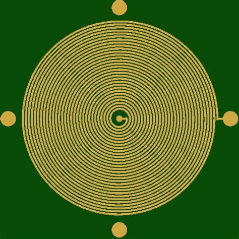
Planar Coils
Planar coils are flat spiral coils formed directly on the surface of a PCB using copper traces. These coils have a low profile and are well-suited for high-frequency applications, such as RF circuits and wireless charging systems.
Designing a PCB Coil
Designing a PCB coil involves several factors, including the desired inductance, current carrying capacity, and operating frequency. The following steps outline the general process for designing a PCB coil:
-
Determine the required inductance: The first step in designing a PCB coil is to determine the required inductance for your application. This value can be calculated using various formulas, depending on the coil type and configuration.
-
Choose the coil type: Based on your application and the required inductance, select the appropriate coil type (air core, ferrite core, toroidal, or planar).
-
Calculate the number of turns: Use the appropriate formula to calculate the number of turns needed to achieve the desired inductance. This calculation will depend on the coil type, core material (if applicable), and the dimensions of the coil.
-
Determine the wire gauge: Select the appropriate wire gauge based on the current carrying capacity and the available space on the PCB. Thicker wire gauges can handle higher currents but require more space.
-
Design the PCB layout: Create the PCB layout for your coil, considering factors such as trace width, spacing, and the number of layers. Ensure that the layout is optimized for your specific application and minimizes EMI.
-
Simulate and test: Use PCB design software to simulate the performance of your coil and make any necessary adjustments. Once the design is finalized, prototype the PCB and test the coil to verify its performance.

Constructing a PCB Coil
Once you have designed your PCB coil and created the PCB layout, you can proceed with the construction process. The following steps outline the general process for constructing a PCB coil:
-
Gather materials: Collect the necessary materials, including the PCB, wire, soldering iron, solder, and any additional components (e.g., core material, insulation, etc.).
-
Prepare the PCB: Clean the PCB and apply a thin layer of solder flux to the coil traces to facilitate soldering.
-
Wind the coil: Carefully wind the wire around the core (if applicable) or onto the PCB traces, following the designed number of turns. Ensure that the wire is tightly wound and evenly spaced.
-
Secure the windings: Use adhesive, tape, or other suitable methods to secure the windings in place and prevent them from unraveling.
-
Solder the connections: Solder the ends of the wire to the designated pads on the PCB, ensuring a strong and reliable connection.
-
Test the coil: Use an LCR meter or other suitable equipment to measure the inductance and resistance of the coil, verifying that it meets the designed specifications.
-
Assemble the device: Integrate the PCB coil into your final device, following the appropriate assembly procedures.

Factors Affecting PCB Coil Performance
Several factors can influence the performance of a PCB coil, including:
-
Core material: The choice of core material (air, ferrite, iron powder, etc.) affects the coil’s inductance, magnetic field strength, and frequency response.
-
Winding geometry: The shape, spacing, and number of turns in the winding affect the coil’s inductance, resistance, and self-resonant frequency.
-
Wire gauge: The thickness of the wire used in the coil impacts its current carrying capacity, resistance, and high-frequency performance.
-
PCB layout: The PCB layout, including trace width, spacing, and the number of layers, can affect the coil’s performance and EMI characteristics.
-
Operating environment: External factors, such as temperature, humidity, and the presence of nearby magnetic materials, can influence the coil’s performance.
Considering these factors and optimizing your PCB coil design accordingly can help ensure optimal performance in your specific application.

Common PCB Coil Applications
PCB coils find use in a wide range of electronic applications, some of which include:
Power Transformers
PCB coils are often used in power transformers to step up or step down voltage levels and provide isolation between circuits. These transformers are essential in power supplies, battery chargers, and other power management applications.
Inductors
PCB coils serve as inductors in various circuits, such as LC filters, switch-mode power supplies, and DC-DC converters. These inductors help smooth current ripples, reduce EMI, and store energy for later use.
RFID Antennas
PCB coils, particularly planar coils, are commonly used as antennas in radio frequency identification (RFID) systems. These antennas enable wireless communication between RFID tags and readers, facilitating asset tracking, access control, and inventory management.
Wireless Charging Coils
PCB coils play a crucial role in wireless charging systems, such as those used in smartphones, wearables, and other electronic devices. These coils enable the transfer of power through electromagnetic induction, allowing devices to charge without physical connections.
Electromagnetic Sensors
PCB coils can be used as electromagnetic sensors, detecting the presence, position, or movement of magnetic objects. These sensors find applications in various fields, including automotive, industrial automation, and medical devices.
FAQ
- What is the difference between an air core and a ferrite core PCB coil?
-
An air core PCB coil has no magnetic core material, while a ferrite core coil features a ferrite core in the center of the winding. Ferrite core coils offer higher inductance and magnetic field strength, making them suitable for low-frequency applications. Air core coils have lower inductance but higher Q factors, making them ideal for high-frequency applications.
-
How do I calculate the inductance of a PCB coil?
-
The inductance of a PCB coil can be calculated using various formulas, depending on the coil type and configuration. For example, the inductance of a planar spiral coil can be approximated using the modified Wheeler formula:
L = (31.33 * µ0 * N^2 * davg) / (16 * davg + 28 * w)
where L is the inductance in henries, µ0 is the permeability of free space, N is the number of turns, davg is the average diameter of the coil, and w is the width of the trace. -
What factors should I consider when choosing the wire gauge for my PCB coil?
-
When selecting the wire gauge for your PCB coil, consider the current carrying capacity and the available space on the PCB. Thicker wire gauges can handle higher currents but require more space. Additionally, keep in mind that thicker wires may have higher resistance and lower high-frequency performance.
-
How can I minimize electromagnetic interference (EMI) in my PCB coil design?
-
To minimize EMI in your PCB coil design, consider the following techniques:
- Use toroidal coils or other closed-loop geometries to contain the magnetic field.
- Optimize the PCB layout by minimizing trace lengths, using ground planes, and routing traces perpendicular to each other.
- Implement shielding techniques, such as copper pours or conductive enclosures, to reduce EMI emissions.
- Use ferrite beads or other filtering components to suppress high-frequency noise.
-
Can I use a PCB coil for wireless charging applications?
- Yes, PCB coils, particularly planar spiral coils, are commonly used in wireless charging applications. These coils enable the transfer of power through electromagnetic induction, allowing devices to charge without physical connections. When designing a PCB coil for wireless charging, consider factors such as the operating frequency, coil size, and coupling efficiency to ensure optimal performance.
Conclusion
PCB coils are essential components in many electronic devices, serving various roles such as transformers, inductors, antennas, and sensors. By understanding the different types of PCB coils, their design considerations, and construction processes, engineers and hobbyists can create custom coils tailored to their specific applications.
When designing a PCB coil, it is crucial to consider factors such as the required inductance, current carrying capacity, operating frequency, and EMI mitigation techniques. By optimizing these parameters and carefully constructing the coil, you can ensure optimal performance in your electronic devices.
As technology continues to advance, the importance of PCB coils in enabling new and innovative applications will only grow. From power management and wireless charging to RFID and electromagnetic sensing, PCB coils will remain a fundamental building block in the ever-evolving landscape of electronics.
No responses yet