What is Schematic-PCB Synchronization?
Schematic-PCB synchronization refers to the process of ensuring that the logical connections represented in the schematic diagram are accurately translated into the physical layout of the printed circuit board (PCB). It involves maintaining consistency between the schematic symbols, net names, and component designators with their corresponding counterparts on the PCB layout.
Effective synchronization between schematic and PCB is essential for several reasons:
-
Error Reduction: By maintaining a tight link between the schematic and PCB, the chances of introducing errors during the design process are significantly reduced. Any changes made in the schematic are automatically reflected in the PCB layout, minimizing the risk of manual errors.
-
Design Consistency: Schematic-PCB synchronization ensures that the logical design represented in the schematic matches the physical implementation on the PCB. This consistency is crucial for proper functionality and manufacturability of the electronic device.
-
Time Savings: With seamless synchronization, designers can save a substantial amount of time that would otherwise be spent manually updating the PCB layout every time a change is made in the schematic. This efficiency boost allows for faster design iterations and shorter time-to-market.
Key Features of Schematic Software for Effective Synchronization
When evaluating schematic software for its synchronization capabilities, there are several key features to consider:
-
Bi-Directional Synchronization: The software should support bi-directional synchronization, allowing changes made in either the schematic or PCB to be automatically reflected in the other. This ensures that both representations of the design remain in sync throughout the design process.
-
Real-Time Updates: Look for schematic software that provides real-time updates between the schematic and PCB. Any modifications made in the schematic should be immediately visible in the PCB layout, and vice versa. This real-time synchronization eliminates the need for manual updates and reduces the chances of discrepancies.
-
Component Library Management: An extensive and well-managed component library is crucial for efficient schematic-PCB synchronization. The software should offer a centralized library that includes schematic symbols, PCB footprints, and associated metadata. Consistent naming conventions and the ability to update components across multiple designs are essential features to look for.
-
Design Rule Checking (DRC): Schematic software with built-in design rule checking capabilities can identify potential issues early in the design process. DRC rules can be set up to check for errors such as missing connections, incorrect pin assignments, or component mismatches between the schematic and PCB. Catching these issues during the schematic phase reduces the likelihood of problems arising during PCB layout.
-
Collaborative Design: In today’s globalized world, design teams often work collaboratively across different locations. Schematic software that supports collaborative design features, such as version control, user permissions, and real-time collaboration, can greatly enhance the efficiency of schematic-PCB synchronization in team environments.

Top Schematic Software for Seamless Synchronization
Now that we have discussed the key features to look for, let’s explore some of the best schematic software options available in the market that excel in schematic-PCB synchronization.
1. Altium Designer
Altium Designer is a comprehensive electronic design automation (EDA) software that offers a powerful schematic capture tool with seamless PCB integration. Its key features include:
- Bi-directional synchronization between schematic and PCB
- Real-time design rule checking (DRC)
- Extensive component libraries with integrated data management
- Collaborative design features with version control and user permissions
- Multi-sheet schematic support for complex designs
Altium Designer’s schematic editor provides a user-friendly interface with drag-and-drop functionality, making it easy to create and modify schematic diagrams. The software’s synchronization capabilities ensure that any changes made in the schematic are automatically reflected in the PCB layout, saving time and reducing errors.
2. OrCAD Capture
OrCAD Capture, part of the OrCAD design suite, is another popular schematic capture software known for its robust synchronization capabilities. Its notable features include:
- Bi-directional synchronization with OrCAD PCB Editor
- Hierarchical schematic design support
- Customizable design rules and constraints
- Integration with component information portals for easy part selection
- Collaborative design features with design data management
OrCAD Capture’s tight integration with OrCAD PCB Editor ensures seamless synchronization between schematic and PCB. The software’s hierarchical schematic design support allows for efficient management of complex designs, while its customizable design rules help catch potential issues early in the design process.
3. KiCad EDA
KiCad EDA is a free and open-source schematic capture and PCB design software that has gained significant popularity in recent years. Despite being free, KiCad offers impressive synchronization capabilities, making it a compelling choice for designers on a budget. Its key features include:
- Bi-directional synchronization between schematic and PCB
- Extensive component libraries with integrated 3D models
- Hierarchical schematic design support
- Customizable design rules and constraints
- Cross-platform compatibility (Windows, macOS, Linux)
KiCad’s schematic editor provides a intuitive interface for creating and editing schematic diagrams. The software’s synchronization capabilities ensure that changes made in the schematic are seamlessly reflected in the PCB layout. With its active community and regular updates, KiCad is a solid choice for those seeking a cost-effective solution for schematic-PCB synchronization.

Best Practices for Effective Schematic-PCB Synchronization
To ensure optimal synchronization between schematic and PCB, consider the following best practices:
-
Establish Naming Conventions: Implement consistent naming conventions for components, nets, and other design elements. This consistency helps maintain clarity and reduces the chances of errors during synchronization.
-
Use Hierarchical Schematic Design: Break down complex designs into smaller, manageable hierarchical blocks. This approach improves readability, facilitates reuse, and simplifies synchronization between schematic and PCB.
-
Leverage Design Constraints: Utilize the design constraint features offered by your schematic software. Applying constraints such as pin assignments, net classes, and design rules early in the schematic phase helps catch potential issues and ensures smoother synchronization with the PCB layout.
-
Perform Regular Design Reviews: Conduct regular design reviews to verify the accuracy and consistency of the schematic and PCB. Catching discrepancies early can save significant time and effort in the later stages of the design process.
-
Collaborate Effectively: When working in a team environment, leverage the collaborative features provided by your schematic software. Use version control, assign user permissions, and establish clear communication channels to ensure seamless collaboration and synchronized design updates.

Schematic-PCB Synchronization Workflow
To illustrate the typical workflow for schematic-PCB synchronization, let’s consider an example using Altium Designer:
-
Create Schematic: Begin by creating a new schematic document in Altium Designer. Place the necessary components, connect them using wires, and assign appropriate net names.
-
Update Component Libraries: Ensure that the component libraries used in the schematic are up to date and contain accurate information, including schematic symbols, PCB footprints, and associated metadata.
-
Run Design Rule Checks: Perform design rule checks (DRC) on the schematic to identify any potential issues, such as missing connections or incorrect pin assignments. Address any flagged errors before proceeding to PCB layout.
-
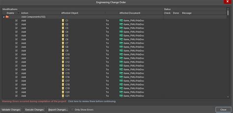
Synchronize with PCB: Once the schematic is complete and error-free, synchronize it with the PCB layout. In Altium Designer, this is achieved through the “Update PCB” command. Any changes made in the schematic, such as added or removed components or net modifications, will be automatically reflected in the PCB layout.
-
Resolve Synchronization Issues: If any synchronization issues arise, such as component mismatches or net discrepancies, resolve them in the schematic and re-synchronize with the PCB. Altium Designer provides clear feedback and guidance to help identify and address synchronization problems.
-
Iterate and Refine: As the design progresses, continue to make necessary changes in the schematic and synchronize them with the PCB layout. The bi-directional synchronization capabilities of Altium Designer ensure that changes made in either the schematic or PCB are automatically reflected in the other.
By following this workflow and leveraging the synchronization features of Altium Designer, designers can maintain a tight link between the schematic and PCB, reducing errors and streamlining the overall design process.
Frequently Asked Questions (FAQ)
-
What is the importance of schematic-PCB synchronization?
Schematic-PCB synchronization is crucial for ensuring that the logical design represented in the schematic matches the physical implementation on the PCB. It reduces errors, maintains design consistency, and saves time by automatically updating the PCB layout when changes are made in the schematic. -
Can I use different schematic and PCB software for synchronization?
While it is possible to use different schematic and PCB software, it is generally recommended to use an integrated solution from the same EDA vendor. Integrated solutions, such as Altium Designer or OrCAD, offer seamless bi-directional synchronization and ensure compatibility between the schematic and PCB tools. -
How can I ensure accurate synchronization between schematic and PCB?
To ensure accurate synchronization, follow best practices such as establishing naming conventions, using hierarchical schematic design, leveraging design constraints, performing regular design reviews, and collaborating effectively with your team. Additionally, choose schematic software with robust synchronization features and follow the recommended workflow for your specific software. -
What should I do if I encounter synchronization issues?
If you encounter synchronization issues, such as component mismatches or net discrepancies, start by reviewing the schematic for any errors or inconsistencies. Make necessary corrections in the schematic and re-synchronize with the PCB. Most schematic software provides feedback and guidance to help identify and resolve synchronization problems. -
Can I synchronize schematic and PCB in real-time?
Yes, many modern schematic software solutions, including Altium Designer and OrCAD Capture, offer real-time synchronization between schematic and PCB. Any changes made in the schematic are immediately reflected in the PCB layout, and vice versa. This real-time synchronization greatly enhances the efficiency and accuracy of the design process.
Conclusion
Schematic-PCB synchronization is a vital aspect of electronic design that ensures consistency, reduces errors, and saves time. Choosing the right schematic software with robust synchronization capabilities is essential for streamlining your design workflow. Altium Designer, OrCAD Capture, and KiCad EDA are among the best schematic software options that offer seamless synchronization with their respective PCB design tools.
By understanding the key features to look for, following best practices, and adopting an efficient synchronization workflow, designers can maximize the benefits of schematic-PCB synchronization. With the right tools and approaches, you can create accurate, consistent, and error-free designs, ultimately leading to successful electronic products.
Remember, investing in reliable schematic software with strong synchronization capabilities is an investment in the quality and efficiency of your electronic design process.

No responses yet