Introduction to the NRF24L01 Wireless Transceiver Module
The NRF24L01 is a popular low-cost 2.4GHz wireless transceiver module commonly used in electronics projects for sending and receiving data wirelessly over short distances. It utilizes the 2.4 GHz ISM band and can operate with baud rates from 250 kbps up to 2 Mbps. This module is a great choice for applications requiring wireless communication between microcontrollers, sensors, and other devices.
The NRF24L01 module uses the SPI communication protocol for interfacing with microcontrollers such as Arduino, Raspberry Pi, and others. It has an onboard PCB Antenna and can achieve a range of up to 100 meters in open space. The module is also quite energy-efficient, with low power consumption during transmission and reception.
NRF24L01 Module Specifications
Here are the key specifications of the NRF24L01 wireless transceiver module:
| Specification | Value |
|---|---|
| Operating Voltage | 1.9V to 3.6V |
| Operating Current (Transmission) | 11.3mA at 0dBm output power |
| Operating Current (Reception) | 13.5mA at 2Mbps |
| Standby Current | 22µA |
| Power Down Current | 900nA |
| Operating Frequency | 2.4GHz ISM band (2.400 – 2.525 GHz) |
| Data Rate | 250kbps, 1Mbps, 2Mbps |
| Output Power | 0dBm, -6dBm, -12dBm, -18dBm |
| Receiver Sensitivity | -85dBm at 1Mbps |
| Range | Up to 100m in open space |
| Antenna | Onboard PCB antenna or external antenna via connector |
| Communication Interface | SPI |
| Operating Temperature | -40°C to +85°C |
| Dimensions | 15mm x 29mm x 1mm |

NRF24L01 Pinout Diagram and Description
The NRF24L01 module has 8 pins that are used for interfacing with a microcontroller and providing power to the module. Here is the pinout diagram for the NRF24L01:
        +---+---+
  CE   -|1  8|-  VCC
  CSN  -|2  7|-  MOSI
  SCK  -|3  6|-  MISO
  GND  -|4  5|-  IRQ
        +---+---+
And here is a description of each pin:
-
CE (Chip Enable): This pin is used to enable/disable the chip. When pulled low, the module is disabled and enters standby mode. When pulled high, the module is enabled for transmission or reception.
-
CSN (Chip Select Not): This pin is used to select the NRF24L01 chip for SPI communication. When pulled low, the module is selected and ready for communication. When pulled high, the module is deselected.
-
SCK (Serial Clock): This pin is used to provide the clock signal for SPI communication.
-
GND (Ground): This pin is connected to ground.
-
IRQ (Interrupt Request): This pin is an active-low interrupt pin. It goes low when new data is received, data has been transmitted, or the maximum number of retries has been reached.
-
MISO (Master In Slave Out): This pin is used for SPI communication, where the NRF24L01 sends data to the microcontroller.
-
MOSI (Master Out Slave In): This pin is used for SPI communication, where the microcontroller sends data to the NRF24L01.
-
VCC (Power Supply): This pin is used to provide power to the module. It should be connected to a regulated 3.3V power supply.
It’s important to note that the NRF24L01 module operates at 3.3V logic levels, so if you’re using it with a 5V microcontroller like the Arduino Uno, you’ll need to use level shifters or voltage dividers to avoid damaging the module.

Connecting the NRF24L01 to a Microcontroller (Arduino)
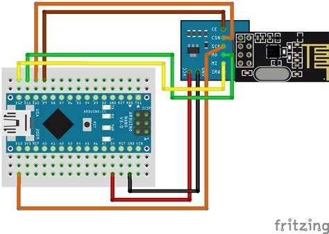
To use the NRF24L01 module with an Arduino, you’ll need to make the following connections:
| NRF24L01 Pin | Arduino Pin |
|---|---|
| VCC | 3.3V |
| GND | GND |
| CE | Any digital pin (e.g., 9) |
| CSN | Any digital pin (e.g., 10) |
| SCK | SCK (13) |
| MOSI | MOSI (11) |
| MISO | MISO (12) |
| IRQ | Not connected (optional) |
Here’s a step-by-step guide to connecting the NRF24L01 to an Arduino:
- Connect the VCC pin of the NRF24L01 to the 3.3V pin on the Arduino.
- Connect the GND pin of the NRF24L01 to a GND pin on the Arduino.
- Connect the CE pin of the NRF24L01 to any digital pin on the Arduino (e.g., pin 9).
- Connect the CSN pin of the NRF24L01 to any digital pin on the Arduino (e.g., pin 10).
- Connect the SCK pin of the NRF24L01 to the SCK pin on the Arduino (pin 13).
- Connect the MOSI pin of the NRF24L01 to the MOSI pin on the Arduino (pin 11).
- Connect the MISO pin of the NRF24L01 to the MISO pin on the Arduino (pin 12).
The IRQ pin can be left unconnected unless you want to use the interrupt functionality of the module.

NRF24L01 Arduino Library and Example Code
To make it easier to work with the NRF24L01 module, you can use the RF24 Arduino library. This library provides an easy-to-use interface for sending and receiving data with the NRF24L01.
To install the RF24 library, follow these steps:
- Open the Arduino IDE.
- Go to Sketch > Include Library > Manage Libraries.
- Search for “RF24” in the search box.
- Click on the “RF24 by TMRh20” library and click “Install”.
Here’s a simple example code that demonstrates how to send data from one Arduino to another using the NRF24L01 module and the RF24 library:
#include <SPI.h>
#include <nRF24L01.h>
#include <RF24.h>

RF24 radio(9, 10); // CE, CSN pins
const byte address[6] = "00001";

void setup() {
  radio.begin();
  radio.openWritingPipe(address);
  radio.setPALevel(RF24_PA_MIN);
  radio.stopListening();
}

void loop() {
  const char text[] = "Hello, world!";
  radio.write(&text, sizeof(text));
  delay(1000);
}
In this example, we create an instance of the RF24 class, specifying the CE and CSN pins. We then set up the radio with a specific address, set the power level to minimum, and put the radio into transmit mode.
In the loop() function, we send the string “Hello, world!” every second using the radio.write() function.
To receive data on another Arduino, you can use the following code:
#include <SPI.h>
#include <nRF24L01.h>
#include <RF24.h>

RF24 radio(9, 10); // CE, CSN pins
const byte address[6] = "00001";

void setup() {
  Serial.begin(9600);
  radio.begin();
  radio.openReadingPipe(0, address);
  radio.setPALevel(RF24_PA_MIN);
  radio.startListening();
}

void loop() {
  if (radio.available()) {
    char text[32] = "";
    radio.read(&text, sizeof(text));
    Serial.println(text);
  }
}
In this code, we set up the radio with the same address, set the power level, and put the radio into receive mode. In the loop() function, we check if data is available using the radio.available() function. If data is available, we read it into a character array and print it to the serial monitor.
NRF24L01 Range and Antenna Options
The NRF24L01 module comes with an onboard PCB antenna that provides a range of up to 100 meters in open space. However, the actual range depends on various factors such as the environment, obstructions, and power level.
If you need to extend the range of the NRF24L01, you can use an external antenna. The module has a U.FL connector that allows you to connect an external antenna. There are several types of antennas you can use, such as:
- Dipole antenna
- Whip antenna
- Yagi antenna
- Patch antenna
When selecting an antenna, consider factors such as the frequency, gain, and directivity. A higher gain antenna will provide a longer range but may be more directional, meaning it needs to be pointed directly at the receiving antenna.
To use an external antenna with the NRF24L01, you’ll need to remove the onboard PCB antenna and solder a U.FL connector to the module. Then, you can connect the external antenna to the U.FL connector.
NRF24L01 Power Saving Modes
The NRF24L01 module has several power-saving modes that can help extend battery life in low-power applications. The module can be put into standby mode or power down mode when not in use to reduce power consumption.
In standby mode, the module maintains its configuration settings but doesn’t transmit or receive data. The current consumption in standby mode is around 22µA.
In power down mode, the module turns off most of its internal circuitry and reduces current consumption to just 900nA. However, it loses its configuration settings and needs to be reconfigured when waking up from power down mode.
To put the NRF24L01 into standby mode, you can use the following code:
radio.powerDown();
To wake the module from standby mode, you can use:
radio.powerUp();
To put the module into power down mode, you can use:
radio.powerDown();
delay(1); // Wait for the module to enter power down mode
To wake the module from power down mode, you need to reinitialize it:
radio.powerUp();
radio.begin();
// Reconfigure the module settings
FAQ
-
What is the operating voltage of the NRF24L01 module?
The NRF24L01 module operates at 3.3V. It’s important not to connect it directly to a 5V microcontroller without level shifting or voltage regulation. -
Can I use the NRF24L01 with a Raspberry Pi?
Yes, you can use the NRF24L01 with a Raspberry Pi. The connections are similar to the Arduino, with the CE and CSN pins connected to any GPIO pins, and the SPI pins connected to the corresponding SPI pins on the Raspberry Pi. -
What is the maximum range of the NRF24L01?
The maximum range of the NRF24L01 with the onboard PCB antenna is around 100 meters in open space. However, the actual range may be less depending on the environment and obstructions. -
Can I use multiple NRF24L01 modules in the same area?
Yes, you can use multiple NRF24L01 modules in the same area. Each module should be configured with a unique address to avoid interference. You can also use different frequency channels to further reduce interference. -
How can I improve the range of the NRF24L01?
To improve the range of the NRF24L01, you can try the following: - Use an external antenna with higher gain
- Increase the transmit power level (note that this will also increase power consumption)
- Reduce obstructions and interference in the environment
- Use a lower data rate (e.g., 250kbps instead of 2Mbps)
- Use a directional antenna pointed towards the receiving module
Conclusion
The NRF24L01 is a versatile and low-cost wireless transceiver module that is widely used in Arduino and other microcontroller projects. By understanding the NRF24L01 pinout and how to connect it to a microcontroller, you can easily add wireless communication capabilities to your projects.
With the RF24 Arduino library, sending and receiving data with the NRF24L01 is straightforward. You can also optimize power consumption by using the module’s power-saving modes and extend the range by using external antennas.
Whether you’re building a remote control, a wireless sensor network, or any other project that requires wireless communication, the NRF24L01 is a great choice. With its low cost, easy integration, and reliable performance, it’s no wonder that the NRF24L01 is one of the most popular wireless modules among hobbyists and makers.
No responses yet