Introduction to the NE5532 Op-Amp
The NE5532 is a dual op-amp IC that features low noise, high slew rate, and wide bandwidth. It is designed for use in high-quality audio applications, such as preamps, mixers, and equalizers. The IC has the following key specifications:
- Low noise: 5 nV/√Hz at 1 kHz
- High slew rate: 9 V/μs
- Wide bandwidth: 10 MHz
- Low distortion: 0.002% at 1 kHz, 10 V p-p output
- High output current: 10 mA
These characteristics make the NE5532 an excellent choice for building high-performance audio PreAmp Circuits.
Basic NE5532 Preamp Circuit
A basic NE5532 preamp circuit consists of a single op-amp configured as a non-inverting amplifier. This circuit provides a simple way to amplify low-level audio signals from sources like microphones or instrument pickups. Here’s how to build a basic NE5532 preamp circuit:
Components Required
- NE5532 IC
- 2x 10 kΩ resistors (R1, R2)
- 2x 1 μF capacitors (C1, C2)
- 1x 100 kΩ potentiometer (VR1)
- 1x 10 kΩ potentiometer (VR2)
- 1x 0.1 μF capacitor (C3)
- 1x 10 μF electrolytic capacitor (C4)
- 1x Audio input jack
- 1x Audio output jack
- 1x Power supply (±12 V)
Circuit Diagram
Step-by-Step Instructions
- Connect the audio input jack to the non-inverting input (pin 3) of the NE5532 through a 1 μF capacitor (C1).
- Connect a 10 kΩ resistor (R1) between the non-inverting input and ground.
- Connect a 100 kΩ potentiometer (VR1) between the inverting input (pin 2) and ground. This potentiometer will control the gain of the preamp.
- Connect a 10 kΩ resistor (R2) between the inverting input and the output (pin 1) of the NE5532.
- Connect a 1 μF capacitor (C2) between the output and the audio output jack.
- Connect a 10 kΩ potentiometer (VR2) between the output and ground. This potentiometer will serve as the volume control.
- Connect a 0.1 μF capacitor (C3) and a 10 μF electrolytic capacitor (C4) in parallel between the positive power supply (+12 V) and ground for power supply decoupling.
- Connect the negative power supply (-12 V) to the appropriate pin on the NE5532.
This basic NE5532 preamp circuit provides a simple way to amplify low-level audio signals. The gain of the preamp can be adjusted using the 100 kΩ potentiometer (VR1), while the output volume can be controlled using the 10 kΩ potentiometer (VR2).

Stereo NE5532 Preamp Circuit
Since the NE5532 is a dual op-amp IC, it can be used to build a stereo preamp circuit. A stereo preamp is useful for amplifying signals from stereo audio sources, such as CD players or MP3 players. Here’s how to build a stereo NE5532 preamp circuit:
Components Required
- NE5532 IC
- 4x 10 kΩ resistors (R1, R2, R3, R4)
- 4x 1 μF capacitors (C1, C2, C3, C4)
- 2x 100 kΩ potentiometers (VR1, VR2)
- 2x 10 kΩ potentiometers (VR3, VR4)
- 2x 0.1 μF capacitors (C5, C6)
- 2x 10 μF electrolytic capacitors (C7, C8)
- 2x Audio input jacks (left and right)
- 2x Audio output jacks (left and right)
- 1x Power supply (±12 V)
Circuit Diagram
Step-by-Step Instructions
- Connect the left audio input jack to the non-inverting input (pin 3) of the first NE5532 op-amp through a 1 μF capacitor (C1).
- Connect a 10 kΩ resistor (R1) between the non-inverting input and ground.
- Connect a 100 kΩ potentiometer (VR1) between the inverting input (pin 2) and ground. This potentiometer will control the gain of the left channel.
- Connect a 10 kΩ resistor (R2) between the inverting input and the output (pin 1) of the first NE5532 op-amp.
- Connect a 1 μF capacitor (C2) between the output and the left audio output jack.
- Connect a 10 kΩ potentiometer (VR3) between the output and ground. This potentiometer will serve as the volume control for the left channel.
- Repeat steps 1-6 for the right channel using the second NE5532 op-amp and components C3, C4, R3, R4, VR2, and VR4.
- Connect 0.1 μF capacitors (C5, C6) and 10 μF electrolytic capacitors (C7, C8) in parallel between the positive power supply (+12 V) and ground for each op-amp for power supply decoupling.
- Connect the negative power supply (-12 V) to the appropriate pins on the NE5532.
This stereo NE5532 preamp circuit allows you to amplify stereo audio signals independently, with separate gain and volume controls for each channel.

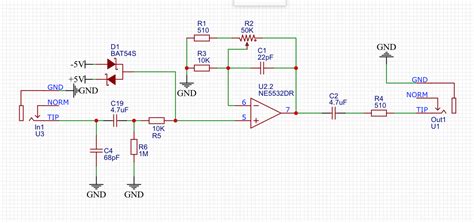
NE5532 Microphone Preamp Circuit
The NE5532 can also be used to build a high-quality microphone preamp circuit. A microphone preamp is designed to amplify the low-level signals from microphones to line-level signals suitable for use with mixers or audio interfaces. Here’s how to build an NE5532 microphone preamp circuit:
Components Required
- NE5532 IC
- 2x 1 kΩ resistors (R1, R2)
- 2x 10 kΩ resistors (R3, R4)
- 1x 1 μF capacitor (C1)
- 1x 10 μF electrolytic capacitor (C2)
- 1x 47 pF capacitor (C3)
- 1x 100 kΩ potentiometer (VR1)
- 1x 10 kΩ potentiometer (VR2)
- 1x XLR microphone input jack
- 1x Audio output jack
- 1x Power supply (±12 V)
Circuit Diagram
Step-by-Step Instructions
- Connect the XLR microphone input jack to the non-inverting input (pin 3) of the NE5532 through a 1 μF capacitor (C1). Use a 1 kΩ resistor (R1) to connect pin 2 of the XLR jack to ground for balanced input.
- Connect a 10 kΩ resistor (R3) between the non-inverting input and ground.
- Connect a 100 kΩ potentiometer (VR1) between the inverting input (pin 2) and ground. This potentiometer will control the gain of the preamp.
- Connect a 10 kΩ resistor (R4) between the inverting input and the output (pin 1) of the NE5532.
- Connect a 1 kΩ resistor (R2) between pin 3 of the XLR jack and the inverting input of the NE5532 for balanced input.
- Connect a 47 pF capacitor (C3) between the output and the inverting input of the NE5532 to improve stability and reduce high-frequency noise.
- Connect a 10 μF electrolytic capacitor (C2) between the output and the audio output jack.
- Connect a 10 kΩ potentiometer (VR2) between the output and ground. This potentiometer will serve as the output level control.
- Connect the positive power supply (+12 V) to the appropriate pin on the NE5532, and connect the negative power supply (-12 V) to another pin.
- Connect the ground of the power supply to the circuit ground.
This NE5532 microphone preamp circuit provides a high-quality, low-noise solution for amplifying microphone signals. The gain can be adjusted using the 100 kΩ potentiometer (VR1), while the output level can be controlled using the 10 kΩ potentiometer (VR2).

NE5532 Phono Preamp Circuit
The NE5532 can also be used to build a phono preamp circuit for amplifying signals from turntables. A phono preamp is designed to amplify the low-level signals from a turntable’s cartridge and apply the necessary RIAA equalization. Here’s how to build an NE5532 phono preamp circuit:
Components Required
- NE5532 IC
- 4x 47 kΩ resistors (R1, R2, R3, R4)
- 2x 1 kΩ resistors (R5, R6)
- 2x 100 Ω resistors (R7, R8)
- 2x 1 nF capacitors (C1, C2)
- 2x 47 nF capacitors (C3, C4)
- 2x 1 μF capacitors (C5, C6)
- 1x 10 μF electrolytic capacitor (C7)
- 1x RCA input jack
- 1x Audio output jack
- 1x Power supply (±12 V)
Circuit Diagram
Step-by-Step Instructions
- Connect the RCA input jack to the non-inverting input (pin 3) of the first NE5532 op-amp through a 47 kΩ resistor (R1) and a 1 nF capacitor (C1) in series.
- Connect a 47 kΩ resistor (R2) between the non-inverting input and ground.
- Connect a 47 nF capacitor (C3) between the inverting input (pin 2) and ground.
- Connect a 47 kΩ resistor (R3) between the inverting input and the output (pin 1) of the first NE5532 op-amp.
- Connect a 1 kΩ resistor (R5) and a 100 Ω resistor (R7) in series between the output of the first NE5532 op-amp and the non-inverting input (pin 5) of the second NE5532 op-amp.
- Connect a 1 μF capacitor (C5) between the non-inverting input of the second NE5532 op-amp and ground.
- Connect a 47 kΩ resistor (R4) between the inverting input (pin 6) and ground.
- Connect a 1 kΩ resistor (R6) and a 100 Ω resistor (R8) in series between the inverting input and the output (pin 7) of the second NE5532 op-amp.
- Connect a 1 nF capacitor (C2) in parallel with the 100 Ω resistor (R8).
- Connect a 47 nF capacitor (C4) and a 1 μF capacitor (C6) in parallel between the output of the second NE5532 op-amp and the audio output jack.
- Connect a 10 μF electrolytic capacitor (C7) between the positive power supply (+12 V) and ground for power supply decoupling.
- Connect the negative power supply (-12 V) to the appropriate pins on the NE5532.
This NE5532 phono preamp circuit provides the necessary amplification and RIAA equalization for turntable signals, allowing you to connect your turntable to a line-level input on your audio system.
Frequently Asked Questions (FAQ)
1. What is the difference between a preamp and a power amp?
A preamp is designed to amplify low-level signals to line-level signals, while a power amp is designed to amplify line-level signals to drive speakers. Preamps typically have high input impedance and low output impedance, while power amps have low input impedance and high output current capability.
2. Can I use the NE5532 for non-audio applications?
While the NE5532 is primarily designed for audio applications, it can be used in other applications that require low-noise, high-speed op-amps. However, there may be more suitable op-amps for specific non-audio applications.
3. What is the maximum supply voltage for the NE5532?
The NE5532 can operate with supply voltages ranging from ±3 V to ±20 V. However, it is recommended to use supply voltages between ±5 V and ±15 V for optimal performance.
4. Can I use the NE5532 in a single-supply configuration?
Yes, the NE5532 can be used in a single-supply configuration, but it requires biasing the input and output signals to half the supply voltage. This can be achieved using a voltage divider and appropriate coupling capacitors.
5. What is the purpose of the capacitors connected in parallel with the power supply?
The capacitors connected in parallel with the power supply (e.g., C3 and C4 in the basic NE5532 preamp circuit) are used for power supply decoupling. They help to filter out high-frequency noise and stabilize the power supply, ensuring optimal performance of the op-amp.
Conclusion
The NE5532 is a versatile and high-performance op-amp that is well-suited for a wide range of audio preamplifier applications. By understanding the basic principles of op-amp circuit design and following the step-by-step instructions provided in this article, you can build various NE5532 Preamp Circuits for different purposes, such as amplifying microphone signals, turntable signals, or line-level signals.
When building these circuits, pay close attention to component values, power supply requirements, and proper grounding techniques to ensure optimal performance and minimize noise. With the right design and implementation, NE5532 preamp circuits can provide high-quality, low-noise audio amplification for your projects.
Remember to always handle electronic components with care, and take necessary precautions when working with electrical circuits. If you are new to electronics or op-amp circuit design, it is recommended to start with simple circuits and gradually work your way up to more complex designs as you gain experience and confidence.
By mastering the art of building NE5532 preamp circuits, you can create custom audio solutions tailored to your specific needs, whether you are a hobbyist, audio enthusiast, or professional. So, grab your soldering iron, gather your components, and start exploring the world of NE5532 preamp circuits today!
No responses yet