What is the MPSA18 Transistor?
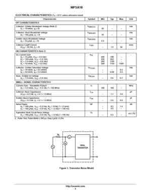
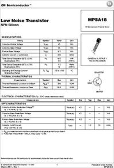
The MPSA18 is a high-voltage, medium-power NPN transistor. It is designed for general-purpose amplification and switching applications. The transistor features a maximum collector-emitter voltage of 300V, a maximum collector current of 500mA, and a power dissipation of 625mW.
MPSA18 Pinout Configuration
The MPSA18 transistor comes in a TO-92 package, which has three pins. The pinout configuration is as follows:
| Pin Number | Pin Name | Description |
|---|---|---|
| 1 | Emitter | The emitter of the transistor |
| 2 | Base | The base of the transistor |
| 3 | Collector | The collector of the transistor |
Here’s a visual representation of the MPSA18 pinout:
       +---------+
       |         |
       |  MPSA18 |
       |         |
 C     |         |     E
---    |         |    ---
 |     |         |     |
 |     |         |     |
 |     |         |     |
 B     |         |     C
---    |         |    ---
       |         |
       |         |
       +---------+
Understanding the Emitter, Base, and Collector
To effectively use the MPSA18 transistor, it’s crucial to understand the role of each pin:
-
Emitter: The emitter is the terminal through which current flows out of the transistor. It is typically connected to the ground or the negative supply voltage.
-
Base: The base is the control terminal of the transistor. A small current applied to the base controls the larger current flowing between the collector and emitter. The base current determines the state of the transistor (on or off).
-
Collector: The collector is the terminal through which current flows into the transistor. It is usually connected to the positive supply voltage or the load.
MPSA18 Specifications
Before using the MPSA18 transistor in your projects, it’s important to familiarize yourself with its key specifications:
- Maximum Collector-Emitter Voltage (VCE): 300V
- Maximum Collector Current (IC): 500mA
- Maximum Power Dissipation (PD): 625mW
- DC Current Gain (hFE): 30-150
- Transition Frequency (fT): 100MHz
These specifications help determine the operating limits and performance characteristics of the MPSA18 transistor.

MPSA18 Applications
The MPSA18 transistor finds applications in various electronic circuits, including:
-
Switching Circuits: The MPSA18 can be used as a switch to control the flow of current in a circuit. It can turn on or off based on the base current.
-
Amplification: The MPSA18 can amplify small signals, making it suitable for use in audio amplifiers, preamplifiers, and signal conditioning circuits.
-
Voltage Regulation: The MPSA18 can be employed in voltage regulator circuits to maintain a constant output voltage.
-
Driving Relays and Solenoids: The high voltage and current handling capability of the MPSA18 make it suitable for driving relays and solenoids.
Example Circuit: MPSA18 as a Switch
One common application of the MPSA18 is as a switch. Here’s an example circuit that demonstrates how to use the MPSA18 to control an LED:
           +12V
            |
            |
            |
            |
           +-+
           | |
           | | R1
           | | 1k
           | |
           +-+
            |
            |
            |
            |
           +-+
           | |
 +5V ------|>| R2
           | | 10k
           +-+
            |
            |
            |
            |
           |-|
B  MPSA18  |/|
     +----|  |----+
     |    |\|     |
     |     |      |
     |     +------|-----+
     |             |     |
     |             |     |
    +++           +-+   +++
    | |           | |   | |
    | | R3        | |   | | R4
    | | 1k        | |   | | 220
    | |           | |   | |
    +++           +++   +++
     |             |     |
     |             |     |
     |             |     |
     |             +-----|>|--- LED
     |                   |
     |                   |
    GND                 GND
In this circuit:
– R1 and R2 form a voltage divider that provides the necessary base current to turn on the MPSA18 transistor when a 5V signal is applied.
– R3 limits the base current to protect the transistor.
– R4 limits the current flowing through the LED.
When a 5V signal is applied to the base of the MPSA18 through R2, the transistor turns on, allowing current to flow through the LED, causing it to light up. When the 5V signal is removed, the transistor turns off, and the LED stops glowing.
Example Circuit: MPSA18 as an Amplifier
The MPSA18 can also be used as an amplifier to increase the strength of small signals. Here’s an example circuit that demonstrates the MPSA18 in a common-emitter amplifier configuration:
                  +12V
                   |
                   |
                  +-+
                  | |
                  | | RC
                  | | 4.7k
                  | |
                  +-+
                   |
                   |
                   |
                   |
                  |-|
           MPSA18 |/|
       +----------|  |-----+
       |          |\|      |
       |           |       |
      +-+          +-------|-----+
      | |                  |     |
Vin --|<| RB               |     |
      | | 10k               |     |
      +-+                  +-+   +++
       |                   | |   | |
       |                   | |   | | RE
       |                   | |   | | 1k
       |                   | |   | |
      GND                 +++   +++
                           |     |
                           |     |
                           |     |
                           +-----|-----Vout
                                 |
                                 |
                                GND
In this amplifier circuit:
– RB sets the base bias current, which determines the operating point of the transistor.
– RC is the collector resistor that defines the voltage gain of the amplifier.
– RE is the emitter resistor that provides negative feedback and stabilizes the amplifier’s operation.
The input signal (Vin) is applied to the base of the MPSA18 through RB. The transistor amplifies the signal, and the amplified output is taken across the collector resistor RC. The voltage gain of the amplifier is approximately equal to the ratio of RC to RE.
MPSA18 Handling Precautions
When working with the MPSA18 transistor, it’s important to follow these handling precautions to ensure proper operation and prevent damage:
-
Static Discharge: The MPSA18 is sensitive to electrostatic discharge (ESD). Handle the transistor with care and use appropriate ESD Protection measures, such as grounding yourself and using ESD-safe packaging.
-
Overheating: Ensure that the MPSA18 operates within its specified temperature range. Excessive heat can damage the transistor. Use a heat sink if necessary to dissipate heat effectively.
-
Reverse Polarity: Avoid reversing the polarity of the voltage applied to the collector and emitter terminals. Reverse polarity can permanently damage the transistor.
-
Overcurrent: Do not exceed the maximum collector current rating of the MPSA18. Excessive current can cause the transistor to fail. Use Current-limiting resistors or fuses to protect the transistor.
Frequently Asked Questions (FAQ)
-
What is the maximum collector-emitter voltage of the MPSA18?
The maximum collector-emitter voltage of the MPSA18 is 300V. -
Can the MPSA18 be used as a switch?
Yes, the MPSA18 can be used as a switch to control the flow of current in a circuit. It can turn on or off based on the base current. -
How much current can the MPSA18 handle?
The MPSA18 can handle a maximum collector current of 500mA. -
Is the MPSA18 sensitive to static discharge?
Yes, the MPSA18 is sensitive to electrostatic discharge (ESD). It is important to handle the transistor with care and use appropriate ESD protection measures. -
What is the power dissipation of the MPSA18?
The maximum power dissipation of the MPSA18 is 625mW.
Conclusion
Understanding the MPSA18 pinout and its functionality is crucial for effectively using this transistor in your electronic projects. The MPSA18 offers versatility, allowing it to be used as a switch, amplifier, voltage regulator, and more. By following the proper handling precautions and considering the transistor’s specifications, you can successfully integrate the MPSA18 into your circuits.
Remember to always refer to the MPSA18 datasheet for detailed information and consult reliable sources when designing your projects. With the knowledge gained from this comprehensive guide, you are now equipped to utilize the MPSA18 transistor to its full potential in your electronic endeavors.
No responses yet