What is the MPSA18?
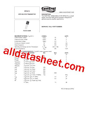
The MPSA18 is a high-voltage, low-power NPN transistor designed for general-purpose amplification and switching applications. It is part of the MPSA series of transistors, which are known for their reliable performance and versatility. The MPSA18 is capable of handling collector-emitter voltages up to 180V and collector currents up to 500mA, making it suitable for a wide range of electronic projects.
MPSA18 Pinout Configuration
To effectively use the MPSA18 transistor, it is essential to understand its pinout configuration. The MPSA18 has three pins: the collector (C), base (B), and emitter (E). The pinout arrangement is as follows:
| Pin Number | Pin Name | Description |
|---|---|---|
| 1 | Emitter | The emitter of the transistor |
| 2 | Base | The base of the transistor |
| 3 | Collector | The collector of the transistor |
It is important to note that the MPSA18 has a TO-92 package, which is a common three-lead plastic package used for small-signal transistors. The TO-92 package has a rounded shape with leads arranged in a triangular pattern.

Electrical Characteristics of the MPSA18
To properly design circuits using the MPSA18, it is crucial to understand its electrical characteristics. The following table summarizes the key electrical parameters of the MPSA18 transistor:
| Parameter | Symbol | Value |
|---|---|---|
| Collector-Emitter Voltage | VCEO | 180V |
| Collector-Base Voltage | VCBO | 180V |
| Emitter-Base Voltage | VEBO | 6V |
| Collector Current | IC | 500mA |
| Collector Dissipation | PC | 625mW |
| DC Current Gain | hFE | 50-800 |
| Transition Frequency | fT | 100MHz |
These electrical characteristics provide a foundation for designing circuits that operate within the MPSA18’s specified limits, ensuring optimal performance and reliability.

MPSA18 as an Amplifier
One of the primary applications of the MPSA18 transistor is as an amplifier. In an amplifier circuit, the MPSA18 is used to increase the strength of a weak input signal, producing a larger output signal. The basic configuration for an MPSA18 amplifier is the common-emitter (CE) amplifier.
Common-Emitter Amplifier
In a common-emitter amplifier, the input signal is applied to the base of the MPSA18, while the output signal is taken from the collector. The emitter is connected to ground or a reference voltage. The following schematic shows a simple common-emitter amplifier using the MPSA18:
In this circuit, the input signal is coupled to the base of the MPSA18 through capacitor C1. Resistor R1 sets the base bias current, while resistor R2 and capacitor C2 form a voltage divider to provide the necessary base bias voltage. The amplified output signal appears across resistor RC, which is connected between the collector and the positive power supply voltage (VCC).
The gain of the common-emitter amplifier can be calculated using the following formula:
AV = -RC / RE
Where:
– AV is the voltage gain
– RC is the collector resistor
– RE is the emitter resistor
By selecting appropriate values for RC and RE, you can achieve the desired gain for your amplifier circuit.

MPSA18 as a Switch
Another common application of the MPSA18 transistor is as a switch. In a switching circuit, the MPSA18 is used to control the flow of current through a load, such as a relay, LED, or motor. When a sufficient base current is applied, the MPSA18 turns on, allowing current to flow through the load. When the base current is removed, the MPSA18 turns off, interrupting the current flow.
Simple Switching Circuit
The following schematic shows a simple switching circuit using the MPSA18 transistor:
In this circuit, the MPSA18 is used to control the current flow through an LED. When a sufficient voltage is applied to the base of the MPSA18 through resistor R1, the transistor turns on, allowing current to flow from the collector to the emitter and through the LED, causing it to illuminate. Resistor R2 limits the current flowing through the LED to prevent damage.
The base current required to turn on the MPSA18 can be calculated using the following formula:
IB = (VCC – VBE) / R1
Where:
– IB is the base current
– VCC is the supply voltage
– VBE is the base-emitter voltage drop (typically 0.7V)
– R1 is the base resistor
By selecting an appropriate value for R1, you can ensure that sufficient base current is provided to turn on the MPSA18 and control the load.
MPSA18 in Darlington Configuration
The MPSA18 can also be used in a Darlington configuration, which combines two transistors to achieve high current gain. In a Darlington pair, the emitter of one transistor is connected to the base of another transistor, effectively multiplying their individual current gains. This configuration is useful when driving loads that require high currents, such as motors or high-power LEDs.
Darlington Pair Circuit
The following schematic shows an MPSA18 Darlington pair circuit:
In this circuit, two MPSA18 transistors (Q1 and Q2) are connected in a Darlington configuration. The emitter of Q1 is connected to the base of Q2, and the collectors of both transistors are tied together. Resistor R1 limits the base current for Q1, while resistor R2 ensures proper turn-off of the Darlington pair.
The total current gain of the Darlington pair can be calculated using the following formula:
βtotal = β1 × β2
Where:
– βtotal is the total current gain of the Darlington pair
– β1 is the current gain of the first transistor (Q1)
– β2 is the current gain of the second transistor (Q2)
By using the MPSA18 in a Darlington configuration, you can achieve extremely high current gains, making it possible to drive loads with high current requirements.
MPSA18 in Voltage Regulation
The MPSA18 can also be used in voltage regulation circuits to maintain a stable output voltage despite variations in the input voltage or load current. One common voltage regulation circuit using the MPSA18 is the series voltage regulator.
Series Voltage Regulator
The following schematic shows a series voltage regulator using the MPSA18 transistor:
In this circuit, the MPSA18 is used as a pass transistor to control the voltage across the load (RL). The base of the MPSA18 is connected to a voltage divider formed by resistors R1 and R2, which sets the output voltage. The Zener diode (D1) provides a stable reference voltage for the voltage divider.
The output voltage of the series voltage regulator can be calculated using the following formula:
Vout = VZ × (1 + R1 / R2)
Where:
– Vout is the regulated output voltage
– VZ is the Zener voltage of D1
– R1 and R2 are the voltage divider resistors
By selecting appropriate values for R1, R2, and D1, you can design a series voltage regulator that provides a stable output voltage for your specific application.
MPSA18 in Audio Circuits
The MPSA18 transistor is also commonly used in audio circuits, such as preamplifiers and power amplifiers. Its high voltage capability and good frequency response make it suitable for audio applications.
Simple Preamplifier Circuit
The following schematic shows a simple preamplifier circuit using the MPSA18 transistor:
In this circuit, the MPSA18 is used as a common-emitter amplifier to amplify the input audio signal. Capacitor C1 couples the input signal to the base of the MPSA18, while capacitor C2 couples the amplified output signal to the next stage. Resistors R1 and R2 set the bias point for the transistor, and resistor RE provides emitter degeneration, which helps to stabilize the circuit and improve linearity.
The gain of the preamplifier can be adjusted by changing the values of RC and RE. Increasing the value of RC or decreasing the value of RE will result in higher gain, while decreasing RC or increasing RE will result in lower gain.
Frequently Asked Questions (FAQ)
- What is the maximum collector-emitter voltage rating of the MPSA18 transistor?
-
The MPSA18 has a maximum collector-emitter voltage rating of 180V.
-
What is the typical current gain (hFE) range for the MPSA18?
-
The typical current gain range for the MPSA18 is 50-800.
-
Can the MPSA18 be used as a switch?
-
Yes, the MPSA18 can be used as a switch to control the flow of current through a load, such as a relay, LED, or motor.
-
How can I increase the current gain when using the MPSA18?
-
To increase the current gain, you can use the MPSA18 in a Darlington configuration, which combines two transistors to multiply their individual current gains.
-
Is the MPSA18 suitable for audio applications?
- Yes, the MPSA18 is suitable for audio applications due to its high voltage capability and good frequency response. It can be used in preamplifier and power amplifier circuits.
Conclusion
The MPSA18 transistor is a versatile and widely used NPN bipolar junction transistor that finds applications in amplification, switching, voltage regulation, and audio circuits. By understanding the MPSA18 pinout and its electrical characteristics, you can effectively integrate this transistor into your electronic projects.
This comprehensive guide has covered the basics of the MPSA18, including its pinout configuration, electrical parameters, and various circuit applications. We have explored common-emitter amplifiers, switching circuits, Darlington configurations, voltage regulators, and audio preamplifiers using the MPSA18.
By following the examples and explanations provided in this guide, you should now have a solid foundation for using the MPSA18 transistor in your own projects. Remember to always consider the specific requirements of your application and design your circuits accordingly.
As with any electronic component, it is essential to handle the MPSA18 with care and operate it within its specified limits to ensure optimal performance and longevity. Always refer to the manufacturer’s datasheet for the most up-to-date and accurate information regarding the MPSA18’s characteristics and usage guidelines.
We hope this guide has been informative and helpful in your journey to understand and utilize the MPSA18 transistor. Happy designing and building your electronic projects!
No responses yet